Download
1 / 24
240 likes | 350 Vues
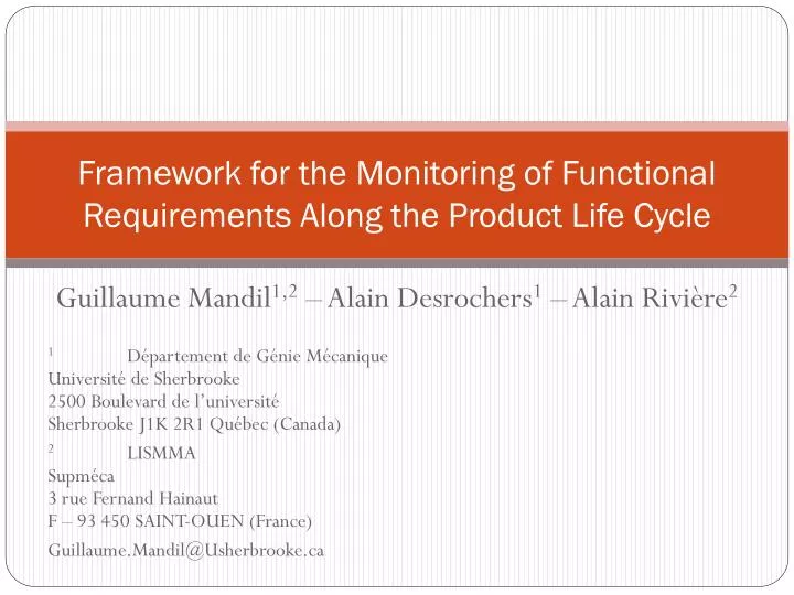
Framework for the Monitoring of Functional Requirements Along the Product Life Cycle. Guillaume Mandil 1,2 – Alain Desrochers 1 – Alain Rivière 2 1 Département de Génie Mécanique Université de Sherbrooke 2500 Boulevard de l’université Sherbrooke J1K 2R1 Québec (Canada)

E N D
Framework for the Monitoring of Functional Requirements Along the Product Life Cycle Guillaume Mandil1,2 – Alain Desrochers1 – Alain Rivière2 1 Département de Génie MécaniqueUniversité de Sherbrooke2500 Boulevard de l’universitéSherbrooke J1K 2R1 Québec (Canada) 2 LISMMASupméca3 rue Fernand HainautF – 93 450 SAINT-OUEN (France) Guillaume.Mandil@Usherbrooke.ca
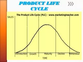
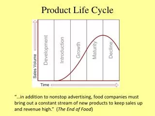
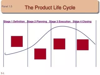
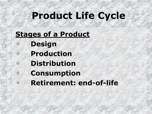
Introduction • Parts within mechanisms are generally specified for the assembly stage of their life cycle • Useful values of Functional Requirements are usually defined under operating conditions (at higher temperature and strains… ) • These 2 occurrences will be referred to as product configurations in this work • Challenge : How to study FR evolution during the product life cycle ? • This work investigates the definition of multiple configurations to integrate part deformation in the FR calculation process
Illustration of the problem At Assembly In Operation Low Temperature (≈20°C) No Centrifugal Force on the blades High temperature Important centrifugal force on the blades How maintain the proper gap between the blades and the frame in these 2 physical states ?
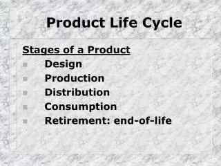
Proposed approaches for tolerancing study along life cycle: [L.Pierre] : approach based on detailed design and Finite Elements simulations • Our approached for early design stages based on : • Early design geometric features [Socoliuc] • TTRS (SATT) for functional association between geometric features [Desrochers] • Parametric design and metric tensor for computations [Serré]
Products requirements across the product life-cycle • Use of a specific set of parameters (orientations and lengths of vectors) to define the mechanism in each relevant use case. • Calculation of functional requirements using each use case set of parameters previously defined. • The specifications for a given requirement under two different states have to be compatible. The environment is not a design variable in itself. • Use of a compact model for avoiding redundancies in data.
Sources of functional requirement variations • Uncertainties due to Tolerances stack-up : analysis of tolerance zones made thanks to existing techniques • Changing environment (variation of mechanical load or temperature) : Elastic deformation of parts.
Functional requirements variations across the life-cycle • Elastic deformation • Variation of tolerance zone width is insignificant relatively to mean dimension variation.
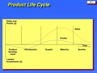
Life-cycle stage Initial State (S1) Final State (S2) Value ofFunctional Requirement - 0 + • Interference possible motion j1 Mean value Functional requirements variation across the life-cycle
1D Application Case: Vcs Vch
1D Application Case:Hypothesis • Assembly temperature 20°C • Cylinder head made of aluminium : • Thermal expansion coefficient 2.38x10⁻⁵ K-1 • Service temperature : 90°C • Camshaft made of steel : • Thermal expansion coefficient 1.20x10⁻⁵ K-1 • Service temperature : 80°C • One dimensional thermal expansion
1D Application Case:Computations & Results • Analysis : calculation of FR with initial dimensions • Synthesis : minimisation of the misalignment in service.
Generalization to 3D application case : • Extension to 3D : Study 3 articulated bars disposed as a tetrahedron. • Use of a vectors as geometrical model. • Use of a metric tensor for the calculation of displacements, configuration under different loads. • Use of thermal dilatation as load variation. • Points A,B and C are supposed to be fixed. C B O A
Method for 3D calculation : • Initial configuration • Mathematical representation • Final configuration • Mathematical representation C’ C B’ O’ B O A’ A Calculated with theoretical formulations Known
Method for 3D calculation : Calculation of the Gif tensor : • Vectorial association : Cholesky factorization • Affine association : coincidence of 2 points • Calculation of deviations C O’ B O A G=
Conclusion • Use of a parametrical representation based on vectors for the mechanism. • Use of theoretical (or FEA) techniques for the calculation of part deformation. • Original idea of representing the mechanism at each stage of its life cycle with a specific set of parameters. • Possibility to model structures and mobile mechanisms. • Method available at early design phases.
Framework for the Monitoring of Functional Requirements Along the Product Life Cycle Guillaume Mandil1,2 – Alain Desrochers1 – Alain Rivière2 1 Département de Génie MécaniqueUniversité de Sherbrooke2500 Boulevard de l’universitéSherbrooke J1K 2R1 Québec (Canada) 2 LISMMASupméca3 rue Fernand HainautF – 93 450 SAINT-OUEN (France) Guillaume.Mandil@Usherbrooke.ca
Method for 3D calculation 1/2 • Vectorization of the model is not detailed here. (obvious) Set of vectors : • Calculation of the metric tensor of the initial configuration. • Calculation of thermal expansion : • Deduction of the metric tensor of the final configuration
Method for 3D calculation 2/2 • Vectorial association between initial and final configuration : Use of a Cholesky factorisation. • Choice of 3 independent vectors : • Calculation of the relation between initial and final configuration: • Deduction of : • Affine association : Calculation of the deviation of points. Here we have :
Product Structure :Links and data exchange Early Design phases models Parametric Model Functional Requirements (GPS) Geometric ModelCAD CAD Deformed Model Finite Elements Simulation MeshResults Simulation Parameters
Design variables and constraints Functional Requirements Individual Dimension Loads : (Temperature, Efforts) Design paradigm : 2 out of 3 of the above elements must be chosen for a design to be fully constrained.
Introduction • Currently, the study of the functional requirement (FR) is done on an ideal model of the mechanism
Product Structure :Assembly representations • Each designing task uses a specific assembly representation. • This framework integrates models related to geometric modelling, tolerance analysis and stress analysis. • In this work we propose to use vectors and loops of vectors as model for assemblies. Geometric elements Points, Lines, Planes,Curves, Surface, … TTRS / MGRESmall displacement Torsor Loops of vectors Meshing B-Rep, CSG models