Download
1 / 1
10 likes | 141 Vues
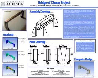
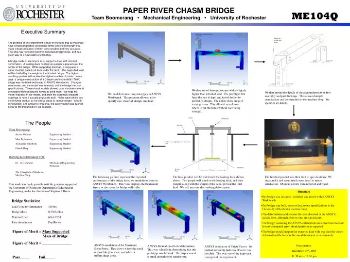
PAPER RIVER CHASM BRIDGE Team Boomerang • Mechanical Engineering • University of Rochester. ME104Q. Executive Summary.

E N D
PAPER RIVER CHASM BRIDGE Team Boomerang • Mechanical Engineering • University of Rochester ME104Q Executive Summary The premise of this experiment is built on the idea that all materials have certain properties concerning stress and yield strength that make virtual simulation of them both possible and very accurate. This idea has revolutionized the manufacturing process, and has given way to a new realm of efficiency. A bridge made of aluminum must support a load with minimal deformation. A loading deck holding two people is placed over the center of the bridge. While supporting this load, a long piece of paper must be pulled out from under the deck. The supported load will be divided by the weight of the finished bridge. The highest resulting quotient will receive the highest number of points. In our case, a unique construction of a C-beam aluminum (6061-T651) bridge was modeled and tested in ANSYS Workbench. Changes were made, and the model was retested, until the bridge met our specifications. These virtual models allowed us to simulate several prototypes without actually having to build them. We kept the model that best fit our needs, and drew the assembly and part drawings to have it actually physically built. Holes were drilled into the finished product at low stress areas to reduce weight. In both construction, and amount of material, the safety factor was pushed as far to the threshold of 1 as possible. 1 inch on inside after bend We then tested these prototypes with a slightly higher than intended load. The prototype that fares the best is kept, and tested further to perfect its design. The colors show areas of varying stress. This allowed us to know where to put the holes without sacrificing strength. We then turned the details of the accepted prototype into assembly and part drawings. This allowed simple manufacture and construction in the machine shop. We specified all details. We modeled numerous prototypes in ANSYS Workbench. This program allowed us to specify size, material, design, and load. Bridge Loading Bar The People Table Top Team Boomerang: Steven Vollmer Max Sicherman Alexandra Wikstrom Patrick Ripp Engineering Student Engineering Student Engineering Student Engineering Student **All excess weight is put onto the wooden plank Working in collaboration with: Dr. D.J. Quesnel The University of Rochester Machine Shop Mechanical Engineering Professor Paper River Wooden Plank 8.5 inches The following pictures represent the expected performance of the bridge based on simulations done in ANSYS Workbench. This view displays the Equivalent Stress, or the stress the bridge will suffer. The final product will be tested with the loading deck shown above. Two people will stand on the loading deck, and their weight, along with the weight of the deck, provide the total load. We will measure the resulting deformation. The finished product was then built to specifications. We measured it and scrutinized every detail to insure satisfaction. Obvious defects were reported and fixed. This work was made possible with the gracious support of the University of Rochester Department of Mechanical Engineering, under the direction of Stephen J. Burns. Summary •Our bridge was designed, modeled, and tested within ANSYS Workbench. •Our bridge was built, more or less, to our specifications in the University of Rochester machine shop. •The deformations and stresses that are observed in the ANSYS calculations, although close to one, are satisfactory. •The bridge, assuming the ANSYS calculations are correct and account for environmental error, should perform as expected. •The bridge should support the expected load with less than the shown deformation (the force in the simulations was overestimated). Presentation: December 13th, 2004 11:30 am – 12:30 pm Bridge Statistics: Load Used for Simulation 315 lbs Bridge Mass 0.27654 lbm Material Used 6061-T651 Parts Attachment Pop Rivets Figure of Merit = Mass Supported Mass of Bridge Figure of Merit = _______________ Pass_____ Fail_____ ANSYS simulation of the Maximum Shear Stress. This shows where the metal is most likely to shear, and where it suffers shear stress. ANSYS Simulation of total deformation. This was valuable in determining that this prototype would work. The displacement is small enough to be satisfactory. ANSYS simulation of Safety Factor. We pushed our safety factor as close to 1 as possible. This was one of the important concepts of the experiment.