Download
1 / 44
510 likes | 921 Vues
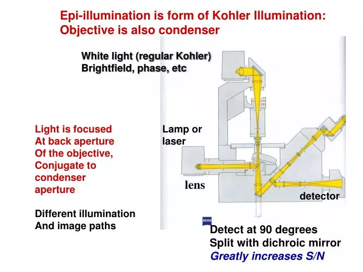
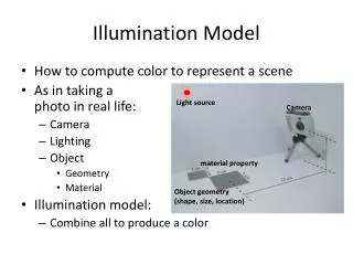
Epi-illumination is form of Kohler Illumination: Objective is also condenser. White light (regular Kohler) Brightfield, phase, etc. Light is focused At back aperture Of the objective, Conjugate to condenser aperture Different illumination And image paths. Lamp or laser. lens.

E N D
Epi-illumination is form of Kohler Illumination: Objective is also condenser White light (regular Kohler) Brightfield, phase, etc Light is focused At back aperture Of the objective, Conjugate to condenser aperture Different illumination And image paths Lamp or laser lens detector Detect at 90 degrees Split with dichroic mirror Greatly increases S/N
Epi-illumination separates light source, Fluorescence signal Second barrier filter Selects signal From background First barrier filter Selects excitation Arc lamp dichroic mirror objective lens specimen
Excitation filter typically interference bandpass • Dichroic is longwave pass • For one dye-maybe no emission filter
Dielectric layers or Metallic layers used as filter coating Reflect, transmit colors of choice by using multilayers
Coatings work by interference Reflectance depends on Wavelength, film thickness material (index*length), incident angle. Fabry-Pérot interferometer
Use of bandpass interference filters in wavelength selection Block 3-6 OD outside of band Transmit 10-50% (worse for UV)
Dichroic Mirrors: separate colors by using coatings Beam separator: Separate different colors (fluorescence) At right angles: used in microscopes Beam combiner: Multiple lasers Transition should be sharp
How CCD Camera Works Serial readout limit speed. A partial solution is using Frame-Transfer.
Efficiency & Signal/Noise? • Collection efficiency of microscopy: ~25% • Detector quantum yield: ~70-90% • Thermal noise • Shot noise (quantum noise): • Read noise (A/D conversion)
CCD Dark counts Cooling methods: Liquid Nitrogen Thermal Electric Thermal Electric in ultrahigh vacuum
EM-CCD • Largely eliminate read noise • Introduces amplification noise • Net effect is S/N improvement for extremely low light level situation
Detecting A Single Fluorescent Molecule? • Size: ~ 1nm • Absorption Cross-section: ~ 10-16 cm2 • Quantum Yield: ~1 Absorbance of 1 molecule = ? How many fluorescence photons per excitation photons?
How to Analyze Single Molecule Measurements (I) -- Histograms Most Probable Value vs Average value
Single molecule fluorescence: experimental considerations • Emission – Wavelength dependence of detectors – Spectral separation from excitation – Efficient detection optics – Autofluorescence and contaminant fluorescence – Photobleaching and ISC – Scatter: • elastic (Rayleigh) • inelastic (Raman) • Excitation – High NA objective lens – “Bright” fluorophores • High extinction coefficient • High quantum yield – Exclude quenchers • particularly molecular oxygen! • O2 scavengers include β-mercaptoethanol (BME), catalase
Back to Single Protein Detection Myosin V -- a motor protein.
De-convolution Microscopy Thompson, RE; Larson, DR; Webb, WW, Biophys. J. 2002,
Photodiode PMT: photomultiplier CCD APD: Avalanche Photodiode
PMT APD Both can work under Single-photon Counting mode
Typical Dark Counts APD CCD -20 C Temperature -70 C Sensitive Area 10-20 m 100-500 m Dark Counts 0.001 e/sec/pixel 10-100 e/sec/pixel
Total Internal Reflection Fluorescence Microscopy TIRFM Total internal reflection: the reflection that occurs when light, in a higher refractive-index medium, strikes an interface with a medium that has a lower refractive index, at an angle of incidence (α1) greater than the critical angle.
Application Example 1 – Cytoskeleton Epi TIRF
Setting up the TIRF microscope Objective-TIRF Prism-TIRF
1980s: start to apply TIR principle to fluorescence and bio-imaging. Daniel Axelrod
Spherical Aberration from Aqueous Sample Sample near glass coverslip Sample in the bulk water
Water immersion with coverslip Water Immersion Objective Fully water immersion
Objective-TIRF Prism-TIRF
Key Points: • NA requirement • Oil immersion • Size of the beam 柳田敏雄 Toshio Yanagida
Through Objective TIRDesign 2: Fiber Optics Optical fiber based light delivery Easy conversion from non-TIR to TIR Compatible with Arc lamp
Other Practical Concerns: • Upright or inverted microscope? • Light sources? • Polarization?


![Real-Time Volume Graphics [06] Local Volume Illumination](https://cdn2.slideserve.com/4770316/real-time-volume-graphics-06-local-volume-illumination-dt.jpg)