Download
1 / 33
330 likes | 461 Vues
CLIC_DDS study. 30.11.2010. CLIC_DDS Study Collaboration. Vasim Khan Alessandro D’Elia Roger Jones. University of Manchester and Cockcroft institute, U.K. CERN, Switzerland. Alexej Grudiev Germana Riddone Vadim Soldatov Walter Wuensch Riccardo Zennaro. Outlook.

E N D
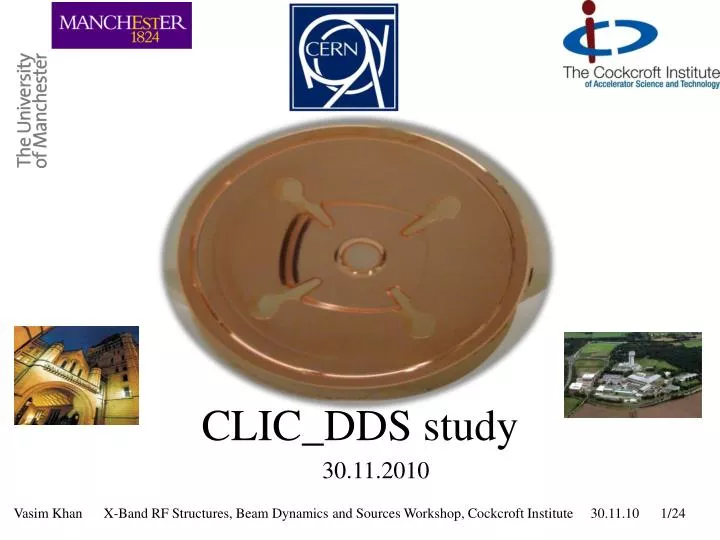
CLIC_DDS study 30.11.2010
CLIC_DDS Study Collaboration • Vasim Khan • Alessandro D’Elia • Roger Jones University of Manchester and Cockcroft institute, U.K. CERN, Switzerland • Alexej Grudiev • Germana Riddone • Vadim Soldatov • Walter Wuensch • Riccardo Zennaro
Outlook • Summary of Optimisation: CLIC_DDS • Overview of test structure: CLIC_DDS_A • High Phase Advance (HPA) Structures: Merits and Demerits • CLIC_DDS_HPA • Future of CLIC_DDS_HPA
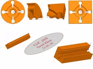
DDS_C DDS_E Circular CLIC_DDS optimisation summary ε=1.38 Circular cell ε=1.38 ε=0.82 Manifold-damped single cell DDS_C DDS_E
CLIC_DDS_A: Monopole properties Esur Max. Values Esur=220 MV/m ∆T = 51 K Pin= 70.8 Eacc_UL=131 MV/m Sc=6.75 W/μm2 RF-beam-eff=23.5% 35*Sc Eacc Pin ∆T CLIC_G Values Esur=240 MV/m ∆T = 51 deg. Pin= 63.8 Eacc_UL=128 MV/m Sc=5.4 W/μm2 RF-beam-eff=27.7% Dashed curves : Unloaded condition Solid curves: Beam loaded condition
CLIC_DDS_A: Dipole properties 24 cells No interleaving Qavg ~1700
High Phase Advance Structures 1) Low group velocity → Less power absorbed during breakdown Ref: R.M. Jones, et. al., SLAC-PUB 8887 CLIC
NLC: Band partitioning NLC: DS1 a = 4.23 mm ψacc : 120°→ 150°:Lowest dipole kick factor reduces by ~ 20% Ref: R.M. Jones, et. al., SLAC-PUB 9467
Dipole mode properties 120deg. Γx = 0.0126 150deg. Γx = 0.021 Cell # 1 a=4.0 mm, t=3.2 mm Cell # 1 a=4.0 mm, t=4.0 mm
DDS_HPA: Merits and Demerits • Reduction in dipole bandwidth from 2.1 GHz to 1.8 GHz • Necessary to reduce bunch population to satisfy wakefield constrains • Luminosity reduction Merits Demerits • Reduced input power • Less power absorbed during breakdown • Kick factors reduced • Better dipole coupling • Cost efficient ?
Enhanced damping: Eight manifolds Four regular and four additional manifolds Significant coupling
Cell # 1 Cell parameters a = 4.3 mm t = 2.6 mm Rc = 9.0 mm Mr = 2.0 mm Mc = 15.1 mm Fundamental mode properties Q=7080 R’/Q=10.356 (kΩ/m) vg=2.44 (%c) Es/Eacc=2.22 Hs/Eacc=4.3 (mA/m) Sc/Eacc=5.45 x 10-4 (W/μm2/Eacc2) fsyn=16.1 GHz Dipole mode properties
Cell # 24 Cell parameters a = 2.5 mm t = 2.8 mm Rc = 8.8 mm Mr = 2.0 mm Mc = 15.1 mm vg=0.32 (%c) fsyn=17.89 GHz
Two Cell result Need improvement Lowest dipole mode properties Δf=2.25 σ=1.78 GHz Δf/fc= 10.5 (%c)
Eight manifolds and Sic As the coupling in the last cell is poor it is important to enhance coupling by optimising the last cell Additional manifold εr=13 tanδ=0.02 NMr=2.8 Damp_r=1 Damping material Regular manifold
Accelerating mode NMr=2 .8 Damp_r=1 εr=14 tanδ=0.04
DDS_HPA_SiC • SiC insertion in an 8-manifold cell improves damping • The SiC properites and dimensions are optimised for Cell # 24 • This optimisation does not improve damping of Cell # 1 • Due to SiC losses, multiple avoided crossings are observed • Need some modification in circuit model to incorporate additional losses (SiC) (future work ?)
Closing remarks • CLIC_DDS_A is being fabricated • CLIC_DDS_A: High power test by 2011 end • CLIC_DDS_HPA: 1) Coupling looks promising 2) Need to improve bandwidth • To be investigated in detail: 1) Eight manifolds 2) DDS_SiC damping 3) Circuit model modification to incorporate SiC losses
Acknowledgments • We have benefited from discussions with Juwen Wang, Zhengai Li and Toshiyasu Higo on X-band structures • Thanks to Igor Syratchev for suggesting to investigate CLIC_DDS_SiC. Thank you
Four manifolds Cell # 1 Cell # 24 Fsyn~15.76 GHz Fsyn~17 GHz Cell parameters a = 3.3 mm t = 3 mm Rc = 9.0 mm Mr = 2.0 mm Mc = 15.1 mm vg = 0.95 (%c) Cell parameters a = 4.6 mm t = 2 mm Rc = 9.0 mm Mr = 2.0 mm Mc = 15.1 mm vg = 3.6 (%c) Cell # 1 Cell # 24
Cell # 1 Cell parameters a = 4.6 mm t = 2 mm Rc = 9.0 mm Mr = 2.0 mm Mc = 15.1 mm vg = 3.6 (%c) Fsyn~15.77 GHz
Cell # 24 Cell parameters a = 3.3 mm t = 3 mm Rc = 9.0 mm Mr = 2.0 mm Mc = 15.1 mm vg = 0.95 (%c) Fsyn~17 GHz
Cell # 1 Cell parameters a = 4.6 mm t = 2 mm Rc = 9.0 mm Mr = 2.0 mm Mc = 15.1 mm vg = 3.6 (%c) Fsyn~15.77 GHz
Cell # 24 Cell parameters a = 3.3 mm t = 3 mm Rc = 9.0 mm Mr = 2.0 mm Mc = 15.1 mm vg = 0.95 (%c) Fsyn~17 GHz
Cell # 1 Cell parameters a = 4.6 mm t = 1 mm Rc = 9.0 mm Mr = 2.0 mm Mc = 15.1 mm vg = 4.84 (%c) Fsyn~15.65 GHz