Download

1 / 66
680 likes | 957 Vues
Superscalar Processors. J. Nelson Amaral. Scalar to Superscalar. Scalar Processor: one instruction pass through each pipeline stage in each cycle Superscalar Processor: multiple instructions at each pipeline stage in each cycle Wider pipeline

E N D
Superscalar Processors J. Nelson Amaral
Scalar to Superscalar • Scalar Processor: one instruction pass through each pipeline stage in each cycle • Superscalar Processor: multiple instructions at each pipeline stage in each cycle • Wider pipeline • Superpipelined Processor: Decompose stages into smaller stages → More Stages • Deeper pipeline Baer p. 75
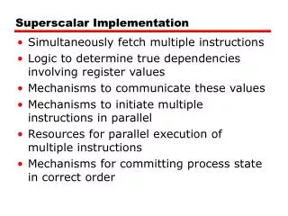
Superscalar • Front end (IF and ID) • Must fetch and decode multiple instructions per cycle • m-way superscalar: brings (ideally) m instructions per cycle into the pipeline • Back end (EX, Mem and WB) • Must execute and write back several instructions per cycle Baer p. 75
Superscalar • In-order (or static) • Instructions leave front-end in program order • Out-of-order (or dynamic) • instructions leave front-end, and execute, in a different order than the program order • WB is called commit stage • must ensure that the program semantics is followed • more complex design Baer p. 76
Limits to Superscalar Performance • Superscalars rely on exploiting Instruction-Level Parallelism (ILP) • They remove WAR and WAW dependences • But the amount of ILP is limited by RAW (true) dependences Data Dependence Graph: Example: S0 S0: R1 ← R2 + R3 S1: R4 ← R1 + R5 S2: R1 ← R6 + R7 S3: R4 ← R1 + R9 RAW WAW S1 WAR S2 WAW RAW S3 Baer p. 76
Limits to Superscalar Performance • Superscalars rely on exploiting Instruction-Level Parallelism (ILP) • They remove WAR and WAW dependences • But the amount of ILP is limited by RAW (true) dependences Data Dependence Graph: Example: S0 S0: R1 ← R2 + R3 S1: R4 ← R1 + R5 S2: R1 ← R6 + R7 S3: R4 ← R1 + R9 RAW WAW S1 WAR RA RB RA S2 WAW RAW S3 Baer p. 76
Limits to Superscalar Performance • Complexity of logic to remove dependencies • Designers predicted 8-way and 16-way superscalars • We have 6-way superscalars and m is not likely to grow Baer p. 76
Limits to Superscalar PerformanceNumber of Forward Paths 1-way: Baer p. 76
Limits to Superscalar PerformanceNumber of Forward Paths 2-way: m-way requires m2 paths paths may become too long for signal propagation within a single clock Baer p. 76
Limits to Clock Cycle Reduction • Power dissipation increases with frequency • Read and Writing to pipeline registers in every cycle. • Time to access pipeline register imposes a bound on the duration of a pipeline stage Baer p. 76
Limits on Pipeline Length • Speculative actions (pe. branch prediction) are resolved later in a longer pipeline • Recovery from misspeculation is delayed 31-stage pipeline Branch Misspred. Penalty: 20 cycles Branch Misspred. Penalty: 10 cycles 14-stage pipeline Baer p. 76
Why the Multicore Revolution? Power Dissipation: Linear growth with clock frequency - Cannot make single cores faster Moore’s Law: Number of transistors in a chip continues the exponential growth - What to do with extra logic? Design Complexity: Extracting more performance from single core requires extreme design complexity. - What to do with extra logic? Baer p. 77
Speed Demons X Brainiacs Pentium III Out-of-Order Superscalar 1999 DEC Alpha In-Order Superscalar 1994 register renaming reorder buffer reservation stations Baer p. 77
Out-of-Order and Memory Hierarchy • Question: Does out-of-order execution help hide memory latencies? • Short answer: No. • Latencies of 100 cycles or more are too long and fill up all internal queues and stall pipelines • Latencies around 100 cycles are too short to justify context switching. • Solution: hardware for several contexts to enable fast context switching → multithreading Baer p. 78
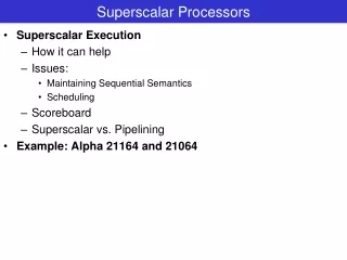
DEC Alpha 21164 4-way in-order RISC virtually indexed Instruction Buffer 32 32 64-bit Miss Address File: merge outstanding misses to the same L2 line. Baer p. 79
21164 Instruction Pipeline Integer pipe 1: shifter and multiplier Integer pipe 2: branches 48-entry I-TLB 64-entry D-TLB Baer p. 79
Brings 4 instructions from I-Cache (accesses I-Cache and ITLB in parallel) Performs branch prediction, calculates branch target slotting stage: steers instructions to units; resolves static conflicts resolves dynamic conflicts; schedules forwardings and stallings Integer pipe 1: shifter and multiplier Integer pipe 2: branches 48-entry I-TLB 64-entry D-TLB Baer p. 80
Example i1: R1 ← R2 + R3 # Use integer pipeline 1 i2: R4 ← R1 – R5 # Use integer pipeline 2 i3: R7 ← R8 – R9 # Requires an integer pipeline i4: F0 ← F2 + F4 # Floating point add i5: i6: i7: i8: i9: i10: i11: i12: Assume no structural or data hazard for these instructions. Baer p. 81
i1: R1 ← R2 + R3 i2: R4 ← R1 – R5 i3: R7 ← R8 – R9 i4: F0 ← F2 + F4 Front-end Occupancy S0 S1 S2 S3 Backend Time: t0 + 1 Time: t0 i5 i1 i2 i6 i3 i7 i4 i8 Baer p. 82
i1: R1 ← R2 + R3 i2: R4 ← R1 – R5 i3: R7 ← R8 – R9 i4: F0 ← F2 + F4 Front-end Occupancy S0 S1 S2 S3 Backend Time: t0 + 2 Time: t0 + 1 i5 i9 i1 i2 i6 i10 i7 i11 i3 i4 i8 i12 Baer p. 82
i1: R1 ← R2 + R3 i2: R4 ← R1 – R5 i3: R7 ← R8 – R9 i4: F0 ← F2 + F4 Front-end Occupancy S0 S1 S2 S3 Backend Time: t0 + 2 Time: t0 + 3 i9 i5 i1 i10 i6 i2 i11 i7 i3 i12 i8 i4 i3 cannot move to S3 because of resource conflict (there are only two integer pipelines) i4 does not move to S3 to preserve program order (it is blocked by i3) Baer p. 82
i1: R1 ← R2 + R3 i2: R4 ← R1 – R5 i3: R7 ← R8 – R9 i4: F0 ← F2 + F4 Front-end Occupancy S0 S1 S2 S3 Backend Time: t0 + 3 Time: t0 + 4 i9 i5 i1 i10 i6 i2 i11 i7 i3 i12 i8 i4 i2 cannot move to the backend because of of RAW dependency with i1. Baer p. 82
i1: R1 ← R2 + R3 i2: R4 ← R1 – R5 i3: R7 ← R8 – R9 i4: F0 ← F2 + F4 Front-end Occupancy S0 S1 S2 S3 Backend Time: t0 + 5 Time: t0 + 4 i13 i9 i5 i1 i14 i10 i6 i2 i15 i11 i7 i3 i16 i12 i8 i4 Baer p. 82
Backend Begins L1 D-cache and D-TLB accesses Decide hit/miss in L1 D-cache and D-TLB Data available if hit in L2 Hit: Forward data (if needed); write to int. or FP register Miss: Start access to L2 Baer p. 82
Scoreboard Speculation Example: a load L, and a dependent use U reach S3 at cycle t If the load hits L1-cache, then schedule L at t+1 and U at t+3. Scoreboard assumes it is a hit. Know if it is a hit or miss here. If it is a miss, abort any dependent instruction already issued. Baer p. 82
Can Compiler Help Performance?(Example) i1: R1 ← Mem[R2] i2: R4 ← R1 + R3 i3: R5 ← R1 + R6 i4: R7 ← R4 + R5 Assume that all instructions are in issuing slot (state S2) at time t.
i1: R1 ← Mem[R2] i2: R4 ← R1 + R3 i3: R5 ← R1 + R6 i4: R7 ← R4 + R5 Compiler Effect S0 S1 S2 S3 Backend Time: t + 1 Time: t i1 i9 i5 i2 i6 i10 i3 i11 i7 i4 i8 i12 Instruction i3 cannot advance to S3 because of an structural hazard: The load in i1 uses an integer pipe to compute the address Baer p. 82
i1: R1 ← Mem[R2] i2: R4 ← R1 + R3 i3: R5 ← R1 + R6 i4: R7 ← R4 + R5 Compiler Effect S0 S1 S2 S3 Backend Time: t + 3 Time: t + 2 Time: t + 1 i1 i9 i5 i2 i6 i10 i3 i11 i7 i4 i8 i12 i2 cannot advance because of the RAW dependency with i1 at t+3 the load continues execution in the back end (2-cycle latency) Baer p. 82
i1: R1 ← Mem[R2] i2: R4 ← R1 + R3 i3: R5 ← R1 + R6 i4: R7 ← R4 + R5 Compiler Effect S0 S1 S2 S3 Backend Time: t + 4 Time: t + 3 i1 i13 i9 i5 i2 i10 i14 i6 i3 i11 i15 i7 i4 i8 i12 i16 Baer p. 82
i1: R1 ← Mem[R2] i2: R4 ← R1 + R3 i3: R5 ← R1 + R6 i4: R7 ← R4 + R5 Compiler Effect S0 S1 S2 S3 Backend Time: t + 4 Time: t + 5 i13 i9 i5 i2 i6 i10 i14 i3 i15 i7 i11 i4 i8 i12 i16 i4 cannot advance because of the RAW dependency with i3 Baer p. 82
i1: R1 ← Mem[R2] i2: R4 ← R1 + R3 i3: R5 ← R1 + R6 i4: R7 ← R4 + R5 Compiler Effect S0 S1 S2 S3 Backend Time: t + 5 Time: t + 6 i9 i5 i13 i6 i10 i14 i3 i7 i11 i15 i4 i12 i8 i16 i4 advances to execution at t+6 and it will be the only integer instruction executing at that cycle. i17 i18 i19 i20 Baer p. 82
i1: R1 ← Mem[R2] i1’: integer nop i2: R4 ← R1 + R3 i3: R5 ← R1 + R6 i4: R7 ← R4 + R5 After Compiler Optimization S0 S1 S2 S3 Backend Time: t + 1 Time: t i1 i4 i8 i1’ i5 i9 i6 i2 i10 i7 i3 i11 Two integer Instructions advance to S3. Baer p. 82
i1: R1 ← Mem[R2] i1’: integer nop i2: R4 ← R1 + R3 i3: R5 ← R1 + R6 i4: R7 ← R4 + R5 After Compiler Optimization S0 S1 S2 S3 Backend Time: t + 2 Time: t + 1 i12 i4 i1 i8 i1’ i13 i5 i9 i2 i14 i6 i10 i3 i15 i7 i11 Baer p. 82
i1: R1 ← Mem[R2] i1’: integer nop i2: R4 ← R1 + R3 i3: R5 ← R1 + R6 i4: R7 ← R4 + R5 After Compiler Optimization S0 S1 S2 S3 Backend Time: t + 2 Time: t + 4 Time: t + 3 i12 i4 i1 i8 i5 i1’ i13 i9 i6 i2 i14 i10 i15 i7 i3 i11 Load in i1 still needs two cycles to execute. Baer p. 82
i1: R1 ← Mem[R2] i1’: integer nop i2: R4 ← R1 + R3 i3: R5 ← R1 + R6 i4: R7 ← R4 + R5 After Compiler Optimization S0 S1 S2 S3 Backend Time: t + 5 Time: t + 4 i12 i16 i4 i1 i8 i13 i17 i5 i9 i18 i14 i6 i2 i10 i3 i15 i19 i7 i11 i2 and i3 can advance to backend together. There is no depencency between them. Baer p. 82
i1: R1 ← Mem[R2] i1’: integer nop i2: R4 ← R1 + R3 i3: R5 ← R1 + R6 i4: R7 ← R4 + R5 After Compiler Optimization S0 S1 S2 S3 Backend Time: t + 4 Time: t + 5 Time: t + 6 i12 i16 i4 i8 i5 i17 i9 i13 i6 i18 i2 i10 i14 i3 i19 i7 i15 i11 i4 still advances to backend at t+6! but now i5 could advance along with i4 * Textbook says that i4 would advance to backend at t+5. Baer p. 82
Scoreboarding “Scoreboarding allows instructions to execute out of order when there are sufficient resources and no data dependences.” John L. Hennessy and David A. Patterson Computer Architecture: A Quantitative Approach Third Edition, p. A-69.
Scoreboarding • Thornton Algorithm (Scoreboarding): CDC 6600 (1964): • A single unit (the scoreboard) monitors the progress of the execution of instructions and the status of all registers. • Tomasulo’s Algorithm: IBM 360/91 (1967) • Reservation stations buffer operands and results. A Common Data Bus (CDB) distributes results directly to functional units Some of this material is from Prof. Vojin G. Oklobzija’s tutorial at ISSCC’97. Baer p. 81
CDC 6600 Group I Not shown: branch unit that modifies the PC Group II Group III Group IV Baer p. 86
CDC 6600 Scoreboard Operation Issue free functional unit? no Stall yes WAW hazard? yes Stall no Issue Baer p. 86
CDC 6600 Scoreboard Operation Dispatch Mark execution unit busy Operands ready? no Stall yes Read operands Baer p. 87
CDC 6600 Scoreboard Operation Execution yes Execution complete? no Stall Notify Scoreboard that it is ready to write result Baer p. 87
CDC 6600 Scoreboard Operation Write result no WAR hazard? yes Stall WAR Example: i0 DIV.D F0, F2, F4 i1 ADD.D F10, F0, F8 i2 SUB.D F8, F8, F14 Has to stall the write of i2 until i1 has read F8 Write Baer p. 87
Scoreboarding Example i1: R4 ← R0 * R2 # Uses multiplier 1 i2: R6 ← R4 * R8 # Uses multiplier 2 i3: R8 ← R2 + R12 # Uses Adder i4: R4 ← R14 + R16 # Uses Adder Baer p. 88
i1: R4 ← R0 * R2 # Uses multiplier 1 i2: R6 ← R4 * R8 # Uses multiplier 2 i3: R8 ← R2 + R12 # Uses Adder i4: R4 ← R14 + R16 # Uses Adder Instructions in Flight Instruction Status Source Reg Units Reg Flags Res. Fi Fj Fk Qj Qk Rj Rk i1 issued R4 R0 R2 1 1 Mult1 Baer p. 88
i1: R4 ← R0 * R2 # Uses multiplier 1 i2: R6 ← R4 * R8 # Uses multiplier 2 i3: R8 ← R2 + R12 # Uses Adder i4: R4 ← R14 + R16 # Uses Adder Instructions in Flight Instruction Status Source Reg Units Reg Flags Res. Fi Fj Fk Qj Qk Rj Rk i1 dispatched issued R4 R0 R2 1 1 i2 issued R6 R4 R8 Mult1 0 1 1 Mult2 Baer p. 88
i1: R4 ← R0 * R2 # Uses multiplier 1 i2: R6 ← R4 * R8 # Uses multiplier 2 i3: R8 ← R2 + R12 # Uses Adder i4: R4 ← R14 + R16 # Uses Adder i2 cannot be dispatched because R4 is not available Instructions in Flight Instruction Status Source Reg Units Reg Flags Res. Fi Fj Fk Qj Qk Rj Rk i1 dispatched execute R4 R0 R2 1 1 i2 issued R6 R4 R8 Mult1 0 1 i3 issued R8 R2 R12 1 1 These values are wrong on Table 3.2 (p. 88) in the textbook Adder Baer p. 88
i1: R4 ← R0 * R2 # Uses multiplier 1 i2: R6 ← R4 * R8 # Uses multiplier 2 i3: R8 ← R2 + R12 # Uses Adder i4: R4 ← R14 + R16 # Uses Adder i4 cannot issue: (i) Adder is busy; AND (ii) WAW dependency on i1 Instructions in Flight Instruction Status Source Reg Units Reg Flags Res. Fi Fj Fk Qj Qk Rj Rk i1 execute R4 R0 R2 1 1 i2 issued R6 R4 R8 Mult1 0 1 i3 dispatched issued R8 R2 R12 1 1 1 Baer p. 88
i1: R4 ← R0 * R2 # Uses multiplier 1 i2: R6 ← R4 * R8 # Uses multiplier 2 i3: R8 ← R2 + R12 # Uses Adder i4: R4 ← R14 + R16 # Uses Adder (No change) Instructions in Flight Instruction Status Source Reg Units Reg Flags Res. Fi Fj Fk Qj Qk Rj Rk i1 execute R4 R0 R2 1 1 i2 issued R6 R4 R8 Mult1 0 1 i3 dispatched execute R8 R2 R12 1 1 Baer p. 88