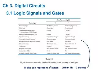
Download
1 / 32
320 likes | 448 Vues
Tutorial 2. Input & output in NEMO5. Michael Povolotskyi , Tillmann Kubis , James Fonseca, Jean Michel Sellier , Daniel Mejia Network for Computational Nanotechnology (NCN) Purdue University, West Lafayette IN. Synopsis. How to control the simulator? T he NEMO5 input deck .

E N D
Tutorial 2. Input & output in NEMO5 Michael Povolotskyi, TillmannKubis, James Fonseca, Jean Michel Sellier, Daniel Mejia Network for Computational Nanotechnology (NCN) Purdue University, West Lafayette IN
Synopsis How to control the simulator? The NEMO5 input deck. Creation of atomic structures. Visualization of the atomistic output (structure). Creation of Finite element mesh. Visualization of finite element data (electric potential).
How to control the simulator? (I) If you have NEMO5 installed in your system: NEMO5 executable MPI execution command mpiexec -n Nnemotransistor.in material parameter database Input deck Two ASCII files that control NEMO5
How to run the code? (III) • User editable files • Simulations are controlled by input deck • Material parameters are stored in a database file • The input deck files are created by a user. • The input deck files are written in “NEMO5 input language” or in Python. • Now we learn the “NEMO5 input language” which is sufficient for any simulation. • The database file is provided, but can be changed by an experienced user.
Synopsis How to control the simulator? Done The NEMO5 input deck. Creation of atomic structures. Visualization of the atomistic output (structure). Creation of Finite element mesh. Visualization of finite element data (electric potential).
The NEMO5 input deck (I) block name • Input deck is an ASCII file – • can be opened by any text editor… Solvers { solver {//solver for the electron density name = quantum_electron type = Schroedinger domain = atomic_structure active_regions= (1,2,3) job_list= (electron_density) eigen_values_solver= krylovschur number_of_eigenvalues= 10 max_number_iterations= 3000 convergence_limit= 1e-12 } } • Input deck consists of blocks • surrounded by “{“ and “}” • a block contains other blocks • and/or options • options are assignments like: • voltage = 1.0 • k_vector = (0.0, 0.5, 0.5) • C++ style comments are supported Input deck fragment
The NEMO5 input deck. (II) There are 3 blocks in the input deck: Structure { } defines material and simulation domains Solvers { } defines simulations that has to be solved, e.g. equations, boundary conditions,iterationprocesses, output, numerical options, etc Global { } defines global variables such as temperature, which database file to use, diagnostic output, etc.
The NEMO5 input deck – the first block “Structure” Structure { } Material { name = Si … } Material { name = SiGe … } Domain { name = device … } Domain { name = contact1 … } Geometry { } materials Domains for simulations Description of the geometry
Synopsis How to control the simulator? Done The NEMO5 input deck. Done Creation of atomic structures. Visualization of the atomistic output (structure). Creation of Finite element mesh. Visualization of finite element data (electric potential).
Creation of atomic structures (I) Structure { } Material { name = Si … } Material { name = SiGe … } Domain { name = device … } Domain { name = contact1 … } Geometry { } User’s steps Input deck sections • Design the device • Chose material and crystal structures • Define where each equation is solved Geometry block Material and domain blocks Solver and domain blocks
Example1: Si/SiGe quantum wire Goal: create Si wire surrounded by a Si0.4Ge0.6 layer Si0.4Ge0.6 Si • Additional requirements: • [100] transport direction • SiGe alloy is represented as a disordered system
Example1. Si/SiGe wire: definition of materials. Material { name = Si tag = core crystal_structure= diamond regions = (1) } Material { name = SiGe tag = substrate crystal_structure= diamond regions = (2) mole_fraction= 0.4 disorder_type= totally_random_alloy } reg.1 Si0.4Ge0.6 reg.2 Si • Each material occupies a region (or regions) • Material definition requires: • name • tag • crystal_structure special parameters for an alloy
Example1. Si/SiGe wire: definition of geometry shapes. reg.2 reg.2 reg.1 reg.1 reg.1 Si0.4Ge0.6 reg.2 Si Full view Cross-section view If two regions overlap, then the biggest priority value wins! Region { shape = cuboid region_number= 1 priority = 2 min = ( 0,2,0) max = ( 10,4,4) } Region { shape = cuboid region_number= 2 priority = 1 min = (3,0,0) max = (7,6,5) } *coordinates are defined in nanometers
Example1. Si/SiGe QWR. Atomistic domain. Two ways to create an atomistic domain: Read-in atomic structure (see discussion forum for details ) Generate atomic structure. (this tutorial) • Any structures (crystals, amorphous, bio molecules, etc…) are possible; • Chemical bonding has to be provided; • Only pseudomorphic lattice is supported; • Chemical bonds are calculated by NEMO5; • Strain relaxation is required for lattice mismatched systems (see tutorial 5)
Example1. Si/SiGe wire: Pseudomorphic domain (I) Pseudomorphic domain is an ideal lattice that consists of materials with the same crystallographic structure. • No defects. • No different lattices in one domain such as GaN and Si together. but… • Different lattice constants are possible. • Some defects in the lattice may be created by NEMO5 (e.g. single impurities, • Lecture 7 ).
Steps to create a pseudomorphic domain. Select the base material. Domain block Create a big lattice by repeating the base material unit cells. Domain block Substitute the base material atoms by the actual material atoms. Remove unnecessary atoms if needed. Geometry block Relax the structure (will be shown in tutorial 5)
Example1. Si/SiGe wire: Pseudomorphic domain (II) Domain{ name = wire_atomistic type = pseudomorphic base_material = core crystal_direction1 = (1,0,0) crystal_direction2 = (0,1,0) crystal_direction3 = (0,0,1) space_orientation_dir1 =(1.0,0.0,0.0) space_orientation_dir2 =(0.0,1.0,0.0) dimension = (30,20,20) periodic = (false, false, false) regions = (1,2) geometry_description = simple_shapes passivate = true random_alloy = true } Base material cell definition Bravais vectors of the cell (miller indexes) Orientation of the crystal directions in the laboratory Cartesian system Repetition of the unit cell. Shaping of the domain Post-processing of the domain
Synopsis How to control the simulator? Done The NEMO5 input deck. Done Creation of atomic structures. Done Visualization of the atomistic output (structure solver). Creation of Finite element mesh. Visualization of finite element data (electric potential of the Poisson solver).
Visualization of atomic structures in NEMO5 Task: visualize atomic structure of our Si/SiGe wire. Solution: Define a solver that outputs the structure in the input deck. Run NEMO5. Use available visualization software. visulaized by Visit
Solver that dumps out structures solver { name = view_shapes type = GeometryVIS geometry_volumes_output= true geometry_volumes_resolution= 20 geometry_volumes_filename= regions.vtk } solver { name = view_atoms type = Structure domain = wire_atomistic output_format= vtk structure_file= Si_SiGe_wire.vtk } Outputs user-defined geometry Outputs an atomistic domain
Let’s seeexample1… Execute tutorial2_1.in input deck Visualize the output using Paraview Modify the input deck: change crystallographic grows directions crystal_direction1 = (1,0,0) crystal_direction2 = (0,1,0) crystal_direction3 = (0,0,1) crystal_direction1 = (1,1,0) crystal_direction2 = (-1,1,0) crystal_direction3 = (0,0,1)
Synopsis How to control the simulator? Done The NEMO5 input deck. Done Creation of atomic structures. Done Visualization of the atomistic output (structure). Done Creation of Finite element mesh. Visualization of finite element data (electric potential).
Finite element (FE) domains. Device simulation requires solution of the Poisson equation: NEMO5 solves the Poisson equation using the FE method. NEMO5 can create the FE mesh automatically: atoms atoms and mesh
Example 2. Si/SiGe wire: creation of a FE mesh domain Atomistic domain “wire_atomistic” FE domain “wire_fem” Domain { name = wire_fem type = finite_elements mesh_from_domain = wire_atomistic output = mesh }
Example 2. Si/SiGe wire: electrostatic boundary conditions (I) Device simulation requires solution of the Poisson equation: The Poisson equation requires boundary conditions: 1. If no boundary conditions are specified, the Neumann boundary condition is applied : 2. In the input deck one can define boundary regions and apply boundary conditions there, e.g. impose a fixed potential value.
Example 2. Si/SiGe wire: electrostatic boundary conditions (II) Device simulation requires solution of the Poisson equation: The Poisson equation solution depends on boundary condition: 1. If no boundary conditions are specified, the Neumann boundary condition is applied. 2. In the input deck one can define boundary regions and apply boundary conditions there.
Example 2. Si/SiGe wire: electrostatic boundary conditions (III) Let’s apply 3 boundary conditions. 3 Boundary_region { shape = cuboid region_number= 1 priority = 1 min = ( -0.1,1.5,-0.2) max = ( 0.2,4.5, 4.5) } Boundary_region { shape = cuboid region_number= 2 priority = 1 min = ( 9.7, 1.5,-0.2) max = ( 10.5,4.5, 4.5) } Boundary_regionn { shape = cuboid region_number= 3 priority = 1 min = ( 3, 0, 5.2) max = ( 7, 6, 5.6) } 2 1 Output of the boundary regions and FE mesh Boundary conditions are applied to the mesh points that are inside the boundary regions.
Example 2. Si/SiGewire: solving the Poisson equation. solver{ name = my_poisson type = Poisson domain = wire_fem fem_output = (potential) boundary_condition{ type = ElectrostaticContact boundary_regions = (1) voltage = 0.0 } boundary_condition{ type = ElectrostaticContact boundary_regions= (2) voltage = 1.0 } boundary_condition{ type = ElectrostaticContact boundary_regions= (3) voltage = 2.0 } }
Synopsis How to control the simulator? Done The NEMO5 input deck. Done Creation of atomic structures. Done Visualization of the atomistic output (structure). Done Creation of Finite element mesh. Done Visualization of finite element data (electric potential).
Let’s run example 2… Execute tutorial2_2.in input deck Visualize the output using Paraview Modify the input deck: change applied voltage. voltage = 1.0 voltage = 2.0
Synopsis How to control the simulator? Done The NEMO5 input deck. Done Creation of atomic structures. Done Visualization of the atomistic output (structure). Done Creation of Finite element mesh. Done Visualization of finite element data (electric potential). Done
Appendix. Input deck editor and database browser. https://engineering.purdue.edu/gekcogrp/software-projects/nemo5/InputDeckEditor/ • PHP based input deck editor: • can show input deck/database in a structured form; • can facilitate input deck edition; • can automatically translate input deck into Python;