Download
1 / 40
410 likes | 618 Vues
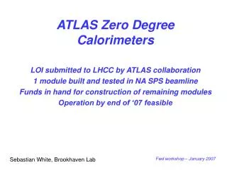
Zero Degree Calorimeters for ATLAS. ZDC Concept ZDC Physics ZDC design ATLAS TDAQ integration ZDC performance (simulation, rad damage, testbeam) Planning/Installation. Sebastian White, Brookhaven Lab. LHCC – January 2007. ZDC in ATLAS.

E N D
Zero Degree Calorimetersfor ATLAS ZDC Concept ZDC Physics ZDC design ATLAS TDAQ integration ZDC performance (simulation, rad damage, testbeam) Planning/Installation Sebastian White, Brookhaven Lab LHCC – January 2007
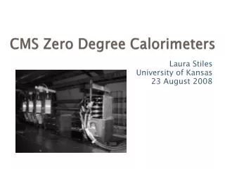
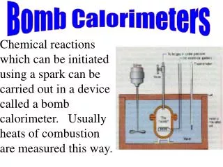
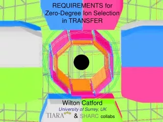
ZDC in ATLAS A Zero Degree Calorimeter (ZDC) is a calorimeter that resides at the junction where the two beam pipes of the LHC become one – at 0° from the pp collisions. It is housed in the shielding unit that protects the S.C magnets from radiation, and measures neutral particle production at 0°. It can play many roles.
z Reaction plane y x Event characterization using forward detectors >>Direction and magnitude of impact parameter, b z Magnitude from complementary parameters Nparticipant=2*A-Nspectator • Spectator neutrons • measure centrality, • Min_min_bias trigger Beam-Beam Counter Mult/1000
Probing small x structure in the Nucleus with gN->jets, in Ultraperipheral Collisions(UPC) di-jet photoproduction-> parton distributions,x2 by g with momentum fraction, x1 4pt2/s=x1*x2 <y>~ -1/2*ln(x1/x2) Signature: rapidity gap in g direction(FCAL veto) x1 x2 ATLAS coverage to |h|<5 units. Pt ~2 Gev “rapidity gap” threshold Analogous upc interactions and gap structure diffractive Non-diffractive
Rates and Kinematics Event yields from a 1 month HI (Pb-Pb) run at nominal Luminosity (4 1026 cm-2s-1). Counts per bin of dpt=2 GeV dx2/x2=+/- 0.25 (with M. Strikman and R. Vogt)
ZDC in pp( Phase II configuration) In pp, the ZDC can measure forward production cross sections for several types of particles at very high energies. This will be useful for adjusting parameters for simulations and models, and for cosmic ray physics where the energy in one proton’s rest frame is 1017 eV – a very interesting energy for extended air showers. What happens when a high energy proton hits the upper atmosphere? The ZDC can find a pi0 in the midst of several neutrons. (1M Pythia events analyzed by a ZDC)
RHIC ZDC as an accelerator tool (in pp) • Van derMeer scan (ZDC coincidence rate • vs. relative beam position) • ZDC (lower curve) bkg free over 4 • orders of magnitude • ZDC also measures beam • displacement (red points) • Useful for crossing angle • commissioning
Aperture limitations from upstream components of the machine
EMCal Module design (1 module only) Light collected from Strips of 1.5 mm quartz Transverse to beam (main energy and timing) And 1 mm quartz rods Projective to beam Latter measure coordinate Of showers.
Strip detail and air Lightguide 648 1.5 mm diameter rods Provides main energy and Timing measurement
Hadronic module with Coordinate readout ( 1 module per arm) Rods are grouped into 4 per readout pixel
Block Diagram of ZDC Readout scheme
ZDC L1 trigger • The ZDC trigger will be used primarily as a 2-arm coincidence (each arm above a preset threshold) in Heavy ion runs • Trigger bits assigned in Central trigger Processor • CTP is designed to accept calibration triggers as well as trigger from small systems like the ZDC
ZDC time, space and energy resolution (Average over active area) ZDC response to neutrons Neutron space resolution Neutron energy resolution Photon space resolution Photon energy resolution Neutron time resolution
Background (PYTHIA / GEANT simulation) Sources of signal and Background Interaction Point Decays in Flight “Walls”
Background (PYTHIA / GEANT simulation) Sources of Signal and Background Interaction Point Decays in Flight “Walls”
Absorbed dose (rad/yr) in TAN at luminosity 1033 cm-2sec-1 ~1 krad MAPMT TAN slot 180 MAPMT PMT PMT PMT PMT 150 ~10 krad 800 ~100 krad 290 Ionization chamber ~1 Mrad ~10 Mrad ~100 Mrad Beam ~1.8 Grad 180 ~100 Mrad ~10 Mrad 30 100 150 150 30 150 150 150 90 1000
We exposed quartz rods at the BNL linac Isotope Producer facility At 5 Grad absorbed dose, light loss corresponds to a 30% deterioration in resolution of coordinate measurement
Test beam exposure in SPS North area parasitic with RP (Oct. ‘06) Single module exposed to 230 GeV proton beam Spectra with 0, 10 and 20 cm steel blocks inserted in the beam Comparison to simulation (note same energy scale used in all Simulations)
Beam tuned to enrich positron component. Peak used to confirm light yield and agreement With simulations
Summary of cables to USA15 Already installed Risetime of fast signals tr= 5 nsec Attenuation 50%
What we are planning • Install full (8 module) ZDC phased with the LHCf run plan • Integrate ZDC into ATLAS DAQ and provide a level1 trigger • Will remove ZDC for highest Luminosity pp runs • Provide a critical role in Heavy Ion program • Important measurements of forward particle production in pp collisions over full acceptance permitted by TAN constraints • Funding from US Nuclear Physics program
Schedule • 1st module completed and tested in beam-no design changes planned • Construction of mechanical modules can begin 2/07 expect completion in 6/07 • Remaining cables installed this spring • Main schedule uncertainty is window for installation of cables and modules • Operation possible at end of ‘07 in conjunction with LCHf detector
Tested correlation between coordinate measurement and Position of 2 mm high beam scintillation counters
Energy resolution for Photons and neutrons (GEANT simulation) Coordinate resolution for photons and neutrons
L1 Calo boards • We require 5 PreProcessor modules • Current production is for 180 modules of which 120 modules needed for L1calo system (KarlHeinz Meier, Heidelberg) • Project would be charged for cost of materials (~10k euro/module) • 1 ROD sufficient
Phasing with LHCf run Phase I Phase II
ZDC Project file (p.1) including Phase II eqpt and labor costs
Up/Down Left/Right 965 Cables 190 94 50 94 520 Left/Right 180 100 180 150 150 760 980 Concept for remote module replacement
Background MARS15:Radiation in TAN, LHCf & ZDC – N.MokhovTAN Integration – CERN, Mar.10, 2006
Assembling module: installing X-Y rods Bare module Rod is put in module and measured Rod is removed, cut to size and replaced Rod is put in module and measured Rod is removed, cut to size and replaced All rods installed