Download
1 / 30
310 likes | 543 Vues
Routing Fundamentals and Subnets. Objectives. Routed protocol IP routing protocols The mechanics of subnetting. Routed Protocol. Routable and Routed Protocols . A routed protocol allows the router to forward data between nodes on different networks.

E N D
Objectives • Routed protocol • IP routing protocols • The mechanics of subnetting
Routable and Routed Protocols • A routed protocol allows the router to forward data between nodes on different networks. • In order for a protocol to be routable, it must provide the ability to assign a network number and a host number to each individual device. • These protocols also require a network mask in order to differentiate the two numbers. • The reason that a network mask is used is to allow groups of sequential IP addresses to be treated as a single unit.
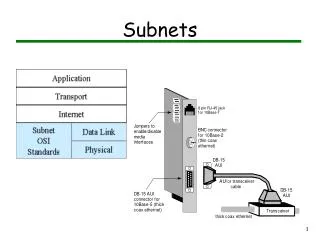
IP as a Routed Protocol • IP is a connectionless, unreliable, best-effort delivery protocol. • As information flows down the layers of the OSI model; the data is processed at each layer. • IP accepts whatever data is passed down to it from the upper layers.
Packet Propagation and Switching Within a Router • As a frame is received at a router interface. • The MAC address is checked to see if the frame is directly addressed to the router interface, or a broadcast. • The frame header and trailer are removed and the packet is passed up to Layer 3. • The destination IP address is compared to the routing table to find a match. • The packet is switched to the outgoing interface and given the proper frame header. • The frame is then transmitted.
Internet Protocol (IP): Connectionless • The Internet is a gigantic, connectionless network in which all packet deliveries are handled by IP. • TCP adds Layer 4, connection-oriented reliability services to IP.
Telephone Calls: Connection-oriented A connection is established between the sender and the recipient before any data is transferred.
Anatomy of an IP Packet • While the IP source and destination addresses are important, the other header fields have made IP very flexible. • The header fields are the information that is provided to the upper layer protocols defining the data in the packet.
Routing Overview • A router is a network layer device that uses one or more routing metrics to determine the optimal path. • Routing metrics are values used in determining the advantage of one route over another. • Routing protocols use various combinations of metrics for determining the best path for data.
Routing Versus Switching • This distinction is routing and switching use different information in the process of moving data from source to destination.
Routed Versus Routing • A routed protocol: • Includes any network protocol suite that provides enough information in its network layer address to allow a router to forward it to the next device and ultimately to its destination. • Defines the format and use of the fields within a packet. • A routing protocol: • Provides processes for sharing route information. • Allows routers to communicate with other routers to update and maintain the routing tables.
Path Determination • Path determination enables a router to compare the destination address to the available routes in its routing table, and to select the best path.
Routing Tables • Routers keep track of the following: • Protocol type • Destination/next-hop associations • Routing metric • Outbound interfaces
Routing Algorithms and Metrics • Routing protocols have one or more of the following design goals: • Optimization • Simplicity and low overhead • Robustness and stability • Flexibility • Rapid convergence
IGP and EGP • IGPs route data within an autonomous system. • RIP, RIPv2, IGRP, EIGRP, OSPF, IS-IS • EGPs route data between autonomous systems • Border Gateway Protocol (BGP)
LinkState and Distance Vector • Examples of distance-vector protocols: • Routing Information Protocol (RIP) • Interior Gateway Routing Protocol (IGRP) • Enhanced IGRP (EIGRP) • Examples of link-state protocols: • Open Shortest Path First (OSPF) • Intermediate System-to-Intermediate System (IS-IS)
Routing Protocols • RIP • RIP v2 • IGRP • EIGRP • OSPF • IS-IS • BGP
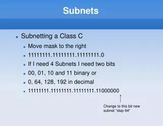
Introduction to Subnetting • Host bits must are reassigned (or “borrowed”) as network bits. • The starting point is always the leftmost host bit. 3 bits borrowed allows 23-2 or 6 subnets 5 bits borrowed allows 25-2 or 30 subnets 12 bits borrowed allows 212-2 or 4094 subnets
Reasons for Subnetting • Provides addressing flexibility for the network administrator. • Each LAN must have its own network or subnetwork address. • Provides broadcast containment and low-level security on the LAN. • Provides some security since access to other subnets is only available through the services of a router.
Establishing the Subnet Mask Address • Determines which part of an IP address is the network field and which part is the host field. • Follow these steps to determine the subnet mask: • 1. Express the subnetwork IP address in binary form. • 2. Replace the network and subnet portion of the address with all 1s. • 3. Replace the host portion of the address with all 0s. • 4. Convert the binary expression back to dotted-decimal notation.
Establishing the Subnet Mask Address • To determine the number of bits to be used, the network designer needs to calculate how many hosts the largest subnetwork requires and the number of subnetworks needed. • The “slash format” is a shorter way of representing the subnet mask: • /25 represents the 25 one bits in the subnet mask 255.255.255.128
Subnetting Class A and B Networks • The available bits for assignment to the subnet field in a Class A address is 22 bits while a Class B address has 14 bits.
Calculating the Subnetwork With ANDing • ANDing is a binary process by which the router calculates the subnetwork ID for an incoming packet. • 1 AND 1 = 1; 1 AND 0 = 0; 0 AND 0 = 0 • The router then uses that information to forward the packet across the correct interface.