Download
1 / 21
210 likes | 368 Vues
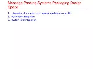
Message Passing Systems Packaging Design Space. Integration of processor and network interface on one chip Board-level integration System-level integration. Integration of Processor and Network Interface. nCube/2, Transputer (INMOS), Blue Gene processor (IBM)

E N D
Message Passing Systems Packaging Design Space • Integration of processor and network interface on one chip • Board-level integration • System-level integration
Integration of Processor and Network Interface • nCube/2, Transputer (INMOS), Blue Gene processor (IBM) • Enables low latency communication
Board-level Integration • A node is implemented on a single board. • Boards include network interface. • Based on commodity processors. • Boards might also include multiple processors. • Multiple nodes (CM5) • Four Sun Sparc1nodes • First level of4-ary tree network • SMP nodes (Altix) • Most current architectures belong to this class.
System-level Integration • Nodes are individual workstations. • Network cards are plugged into IO-Bus. • Networks used are high-speed commodity networks, Myrinet, Quadrix and Infiniband. • Such clusters based on conventional SMP nodes are also used in high-availability services, such as databases, due to the independence of the nodes.
Communication Architecture Design Space • Physical DMA • User-level access • Dedicated message passing processing
Physical DMA Length Length Address Address Ready Ready NETWORK Status/Inter Status/Inter CMD CMD MEMORY Proc MEMORY Proc
Properties • DMA: address, length, and status registers are memory mapped or privileged instructions are used to access them. • Usually physical addresses. • If a send request is done, a trap to the OS is executed. • Incoming messages are blindly deposit into memory. Input channels have to be open all the time to avoid deadlock. • Message arrival will cause an interrupt. • Message handling is usually implemented in kernel to ensure protection. • Messages are copied into system buffer. Kernel adds route information etc. • Some information like error correction code can be added by hardware • Protocol overhead very high for shared address space. A context switch occurs for each remote access.
User-Accessible FIFOs Status/Inter Status/Inter MEMORY MEMORY Proc Proc NETWORK User/System
Properties • Distinguishes user and system-level messages. • No DMA • Processor writes into FIFOs that are memory mapped. • Network interface performs protection check, translation of logical to physical node number, and error checking. • User-level messages are delivered without kernel intervention. • Separate FIFO for user and system messages • User messages remain in FIFO until handled (polling) while system messages are handled via interrupts. • In case of back pressure, also user level messages have to be handled via interrupts. • Some state of the parallel application is in the FIFOs and has to be saved if programs are checkpointed or swapped.
Dedicated Communication Coprocessor MEMORY MEMORY Status/Inter Status/Inter ComputeProc ComputeProc CommProc CommProc NETWORK System mode User mode
Dataflow between Main and Communication Processor MEMORY MEMORY Status/Inter Status/Inter ComputeProc ComputeProc CommProc CommProc NETWORK System mode User mode
Properties • Communication processor can run in privileged mode. • Clean abstraction since all hardware details are handled by communication processor. • Complex protocols can be implemented, e.g. virtual shared memory • Efficiency is influenced by cache coherency protocol • Example: Intel Paragon, ASCI Red
Communication Processor integrated in Network Interface MEMORY MEMORY CP CP Compute Proc Compute Proc NETWORK
VIA and Infiniband • VIA (Virtual Interface Architecture) • Standardized user-level networkinterface • Specificationof the softwareinterface not the NIC implementation • Can befullyimplemented in the hardware NIC ormajorpartsof the protocollprocessingcanbe on-loaded on the hostprocessor. • Allowstobypass the OS on the datapath • Consumersacquireoneormorevirtualinterfaces via the kernelagent (controlpath) • Efficientsharingof NICs • Gettingmoreimportant in multicoreprocessors
Virtual Interface • VI consistsof • Send and receivequeue (Queue Pair – QP) • Consumer putsworkrequests (WR) in the queuesinsteadofdirectlyaccessing the networkadapter • Send requests • Usuallycontain a virtualaddress and a length • Multiple blockscanbespecified for hardware-assistedscatter/gather • Short messages: requestmightcontain the payloadalready • Receiverequests • Onlycontainvirtualaddressreferences
Notificationofnewrequests • Eachqueuehas a doorbellregister in the VI networkadapter • A storeto the doorbellsignalsnewwork. • The adapterkeepstrackof all outstandingrequests and processesthemautonomously. • VIs areasynchronousinterfaces
Notificationoffinishedrequests • Completionqueue • Every workqueuecanbeassociatedwith a completionqueue • Consumer canrequest a completionqueueelement (CQE)
Kernel agent • Device driverprovidedby NIC vendor • Responsible for • settingup, managing and terminatingnetworkconnectionsassociatedwith a VI • Error handling and interruptprocessing • Management ofsystemmemoryusedby the NIC
Zero-Copy Interface • WR includevirtualaddressesto the buffers in userspace • Applicationprogramscannottranslate the virtualaddressesintophysicaladdresses. • TCP/IP stacks use ownmemorybuffers and copy the datainto the buffers. • IO devices needtobeabletotranslatevirtualaddressesintophysicaladdresses need for own MMU • VIA requires the memorytobepinned. • Applicationsregister the addressrangeswithkernelagent • Itpins the memoryand • setsup the translationtables. • Thus settingup a communicationis expensive!