Download
1 / 60
690 likes | 965 Vues
Networks and the Computer Network Interface Card. Presented by: Daniel D. Kochmanski Michael A. DiVito. Advantages of Networks Allow groups of users to exchange information and share data. Allow easy and efficient communication among individuals, including e-mail.

E N D
Networks and the Computer Network Interface Card Presented by: Daniel D. Kochmanski Michael A. DiVito
Advantages of Networks • Allow groups of users to exchange information and share data. • Allow easy and efficient communication among individuals, including e-mail. • Allow users to share peripherals such as printers, scanners, fax machines, and other devices.
Local Area Networks (LANs) and Internetworks • A Local Area Network is also known as an Intranet. It works within a limited geographical area. i.e. within one building or complex • Internetwork is a network 100 or more computers at distances in excess of 1000 feet.
Wide Area Networks (WANs) and the Internet • Wide Area Network (WAN) – span distances measured in miles. i.e. two or more separate LANS linked together • Internet – global WAN internetwork; includes millions of machines and users on the world wide web connected via Network Interface Cards inside each computer.
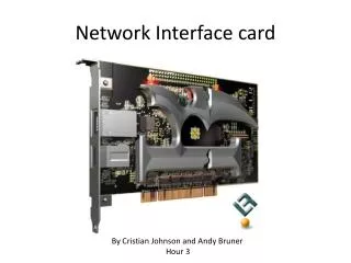
Network Interface Card (NIC) • Also known as a Network Adapter. • Integrated circuit board that plugs into the internal circuitry of the computer. • Allows the members of a local-area network to communicate with each other. • NIC is the physical interface from the computer or peripheral to the medium. • The Medium may be physical cable, such as twisted pair wiring, coaxial cable, fiber optic or even wireless.
Network Cards Convert Data from Parallel to Serial, and vice versa • Most computers use parallel data lines internally to send data between the CPU and the adapter cards. This is called a Bus. • Most networking media transmit data in a single line, called serial transmission. • The NIC translates parallel into serial for outgoing messages and serial into parallel for incoming messages. • Prior to the invention of NICs, data was sent via serial ports on the computer.
RX TX Grnd TX RX Grnd First Computer Networks usedSerial Communications Ports • Serial Com ports use the RS232 standard • DB9 or DB25 type connector • + / - 12volts • Serial means one bit at a time. • Uses • Networking computers • Modem • Mouse & Printers, which are somewhat historical now
Asynchronous Communications • Both ends agree to a protocol and a speed. • i.e. Protocol 1 start bit, 1 stop bit, 1 parity bit & 7 data bits. Speed (baud) 300 - 115,200 bps • Sender transmits start bit and both transmitting and receiving clocks start almost simultaneously. • Data is transmitted • Each clock is now working independently. The block of data is short enough so that clocks do not significantly drift out of sync. • Next block of data causes the clocks to be reset.
Sending a character 1 0 0 0 0 0 1 Line Idle Line Idle Data Bits Parity bit Start bit Stop bit
Receiving a character Receiver’s clock Receiver reads voltage at each agreed interval Clock Start Signal Line Idle Line Idle Data Bits Parity bit Stop bit Start bit
Parallel Data Transmission • Used on a Computer’s Bus where the adapter card plugs in. • i.e. ISA or PCI card bus slots • Used for the parallel LPT port where the printer or scanner plugs in. Parallel ports have: • 5Volt Logic. • Transmission of 1 Byte at a time or 8 bits. • Bi-directional capabilities. Grnd Grnd D A T A Handshake
Understanding the Bus inside the Computer • Bus width refers to number of parallel lines, each able to move one bit at a time. • Industry Standard Architecture (ISA) slots have an 8-bit or 16-bit bus. • Peripheral Component Interconnect (PCI) slots have a 64 bit bus and are the most popular bus used today.
The Network Interface Card’s Transceiver • NICs access the transceiver to transmit data onto the cable. • Most NICs include the transceiver. • Some Ethernet NICs offer multiple interfaces as you will soon see but most are designed for a specific medium. • Newer NICs generally have only one type of media connector.
Network Interface Card Data Packets • Packets are basic units of data for network transmission and reception. • NICs create packages of data bits called packets, then: • Transmit packets serially onto the network medium, and • Act as a gatekeeper, allowing only inbound packets intended for its computer via an electronic serial number known as a MAC address.
The MAC Address • NICs have a unique identifier, called a Media Access Control (MAC) address. • It is programmed into a ROM chip on the NIC. • It’s a 48-bit number, written as six two-digit hexadecimal numbers separated by colons. • The first part identifies the manufacturer. • The second part is unique to each NIC.
IP Address • Network Cards can have a second address called an IP address. • IP Address is software configurable. • IP currently uses 32 bits split into four sections separated by dots. • i.e. 165.255.110.133 – These are decimal values. • Only used in certain network protocols such as TCP/IP.
Network Protocols • Network protocols are a common set of data transmission rules that: • define how to interpret signals and identify individual computers. • initiate and end networked communication, • manage information exchange across the network medium. • Protocols include TCP/IP, NetBEUI, IPX/SPX, and NWLink
OSI Reference Model Structure For Networking • Breaks networked communications into seven layers. Layers help clarify the process of networking. • Application • Presentation • Session • Transport • Network • Data Link • Physical
Each layer of the OSI model communicates and interacts with layers immediately above and below it. • Each layer is responsible for the different aspects of data exchange. • Each layer puts an electronic envelope around data as it sends it down the layers or removes it as it travels up the layers for delivery.
Data Flow • Data is broken into packets or PDUs as it moves down the stack. • PDU stands for protocol data unit, packet data unit, or payload data unit. • Packets are a self-contained data structure from one layer to another. • At the sending end, each layer adds special formatting or addressing to the packet. • At the receiving end, each layer reads the packet and strips off information added by the corresponding layer at the sending end.
Packet Structure • Each packet contains: • Address of the target machine • Address of the source machine • Encapsulated Data • Error Checking Data • The receiving machine checks all the packets. It accepts those with it’s address, then replies with an acknowledgement.
Network Interface Card Data Encapsulation Source Serial # (48), Destination Serial # (48) and Protocol type Source IP (32), Destination IP(32) Offset in the byte stream, Acknowledgement, port number, connection number HELLO THERE DATA IP Datagram Ethernet Packet TCP Header HELLO THERE Trailers
The Basic Ethernet Frame Format contains the following seven fields • Preamble (PRE)—Consists of 7 bytes and is an alternating pattern of ones and zeros that tells the receiving stations that a frame is coming. • Start-of-frame delimiter (SOF)—Consists of 1 byte. • Destination address (DA)—Consists of 6 bytes and identifies which station should receive the frame. • Source addresses (SA)—Consists of 6 bytes and it identifies the sending station. • Length/Type—Consists of 4 bytes and indicates the number of MAC-client data bytes. • Data—Is a sequence of 1500 bytes maximum. • Frame check sequence (FCS)—Consists of 4 bytes and this sequence contains a 32-bit cyclic redundancy check (CRC).
Basic MAC Data Frame Format Transmission order, left to right, bit serial. D
Configuring a Network Interface Card • This involves three settings: • Interrupt Request line (IRQ) • Base Input/Output (I/O) port • Base memory address • In older computers, the user needed to supply the IRQ and base I/O port. Currently Plug and Play operating systems have automated this task and default values are normally assigned.
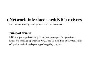
Driver Software for the NIC • This is a small specialized program that manages communications between the operating system and the NIC. • Earlier, each NIC vendor built its own driver. • Now, operating system vendors define drivers for NICs.
Network Layout Design • The Physical Topology refers to physical layout including computers, cables, and other resources on the network. • The Logical topology refers to how data travels between computers on the network.
Today’s network designs are based on three topologies: • Ring whichconnects computers to form a continuous circular loop. • Bus which consists of a series of computers connected along a single cable segment. • Star whichconnects computers via a central connection point known as a hub or switching hub.
Two Types of Coaxial Cable used as a Bus • Thin Ethernet (also called thinnet) designated by the Institute of Electrical and Electronics Engineers (IEEE) as 10Base2 • Thick Ethernet (also called thicknet) designated by IEEE as 10Base5 • Each of these types of cables is terminated with BNC connectors.
Understanding IEEE Cable Designations • 10Base2, for example, refers to a total bandwidth of 10 Mbps, baseband signaling, and the maximum cable segment length as designated in hundreds of meters. • 10Base2 means 200 meters including patch cables • 10Base5 means 500 meters
Star Topology • This is the most common topology in today’s networks. • It connects computers to a central hub that receives and transmits signals to all devices on the network. • Data is addressed and sent in packets to a specific MAC address found inside the computer’s Network Interface Card. • There is ease in troubleshooting because the failure of a single computer or cable does not affect the entire network.
Unshielded Twisted-Pair (UTP) wire is the most common cable used in a Star topology • IEEE specifies that the most popular form of LAN cabling is 10BaseT and 100BaseT • T means Twisted-Pair wire. • Normally 4 sets of twisted-pairs = 8 wires. • The maximum length of a 10BaseT or a 100BaseT segment is 100 meters or 328 feet. This is called the channel link and includes the necessary patch cable at each end of the basic link. • Twisted-Pair wire is also used for telephone systems.
Twisted-Pair Wire Categories • Category 1 or 2: carries voice and low speed data • Category 3: has a bandwidth up to 10 Mbps. It’s used with older networks such as 10BaseT Ethernet. It’s still commonly used for telephone networks today. • Category 4: has a bandwidth up to 16 Mbps and was formally used for 16 Mbps token ring networks. • Category 5: has a bandwidth up to 100 Mbps and is used with 100BaseT Ethernet. • Category 5e or 6: is used for Gigabit Ethernet known as 1000BaseT.
Twisted-Pair Connectors • Both Shielded Twisted-Pair and Unshielded Twisted-Pair wire use RJ-45 modular connectors. • These are similar to the two wire RJ-11 or four wire RJ-14 modular connectors used for the telephones in your house. • RJ-45 is larger and uses eight wires.
In a star topology, the network gear at the center can be a hub or a switching hub. • With a hub, data is sent from one computer to every other computer on the hub simultaneously. • While a switch, as it’s commonly called, maintains address tables for each connection. • On a switch, traffic is sent only to the port for which the data is destined. • A switch allows all pairsof stations to communicatesimultaneously at topspeed. HUB
Simple Router • This router is connected to the LAN and also has a WAN (Internet) connection. • One purpose for the router is to act as a secured “gateway” protecting your network from intruders on the Internet. It uses Network Address Translation (NAT) to perform this function. NAT simply means that the router has it’s own IP address on your network and also has a uniquely different IP address on the Internet. Router World Wide Web
Types of Network Interface Cards • Fiber-Optic Network Interface Cards work on a Fiber-Optic cabled network. • Infrared networking uses infrared light to transmit data from one device to another. • Wireless network cards with antennas operate on a wireless network with a wireless hub. • Copper wired Network Interface Cards work on coax cable or twisted-pair wire.
10Mbs Ethernet Card with an ISA Slot Mounting bracket 10baseT RJ45 Socket Status LEDs Each network card has a unique 48 bit identifier known as the Media Access Control (MAC) number. 10Base2 BNC Connector
Electronic Components on the Network Interface Card • Resistors • Diodes • Capacitors • Coils • Crystals • Integrated Circuits such as the Realtek Fast Ethernet controller chip shown next.
Features of the Ethernet Controller • Scrambling: All the encoded data is passed to the data scrambler to reduce EMI by spreading the power spectrum using a 10-bit scrambler seed loaded at the beginning. • Equalizer and Baseline Wander: High speed signals over unshielded (or shielded) twisted pair cable will experience attenuation and phase shift. These effects depend on the signal frequency, cable type, cable length and the cable connectors. Robust circuits in the transceiver provide reliable adaptive equalizer and baseline wander compensation for amplitude attenuation and phase shift due to transmission line parasitics. • 4B/5B encoding procedure: Each 4-bit data nibble (representing half of a data byte) is mapped into a 5-bit binary code-group that is transmitted bit-serial over the link.
Full Duplex and Half Duplex Operation of Transceiver • The transceiver can operate in either full duplex or half duplex network applications. • In full duplex, both transmission and reception between the network interface cards can take place simultaneously. • In half duplex mode, only one network card can transmit at a time.