Download
1 / 9
100 likes | 390 Vues
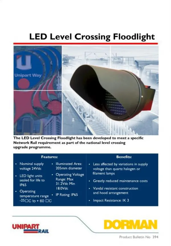
Railway Level Crossing Lights. By: Returaj Burnwal Kunal Raunak Dhananjay Kr. Gupta Krishna Kumar. Description.

E N D
Railway Level Crossing Lights By: ReturajBurnwal Kunal Raunak Dhananjay Kr. Gupta Krishna Kumar
Description Our project deals with the modern way of railway signaling system. Currently our railway system uses sensors to detect the incoming of the train, which actually involves complicated circuit designing, programming for the same and a huge sum of money. So, in our project we have used some basic devices to do our required purpose WITH OUT INVOLVING SENSORS.
Parts Required • Resistors: 680 ×3, 1k ×3, 33k, 47k, 82k, 270k • Capacitors: 0.1µF ×3, 10µF radial ×2 • Red LED (3mm best) ×2 • Amber light • 555 timer IC ×3 • 8-pin DIL socket for IC ×3 • On/Off switch • Battery clip • Push button
555 Timer The 555 timer IC is an integrated circuit (chip) used in a variety of timer, pulse generation, and oscillator applications. It is divided into three types based on their circuit design: • Monostable -In this mode, the 555 timer acts as a "one-shot" pulse generator. The pulse begins when it receives a signal at the trigger input that falls below a third of the voltage supply and stops when voltage supply exceeds two third . • Bistable- In bistable mode, the 555 timer acts as a basic flip-flop. • Astable- In astablemode, the 555 timer puts out a continuous stream of rectangular pulses having a specified frequency.
Working Of Circuit The trigger present in the left corner creates a pulse which triggers the monostable timer and helps in glowing of amber light, further setting the bistable timer to activation, which initiates the astable mode creating continuous rectangular pulses setting LEDs to action. When train passes off cancelation trigger cancel of the created pulse and hence the circuit is turned off.
REFERENCES • http://en.wikipedia.org/wiki/555_timer • http://www.kpsec.freeuk.com/