Download
1 / 15
150 likes | 159 Vues
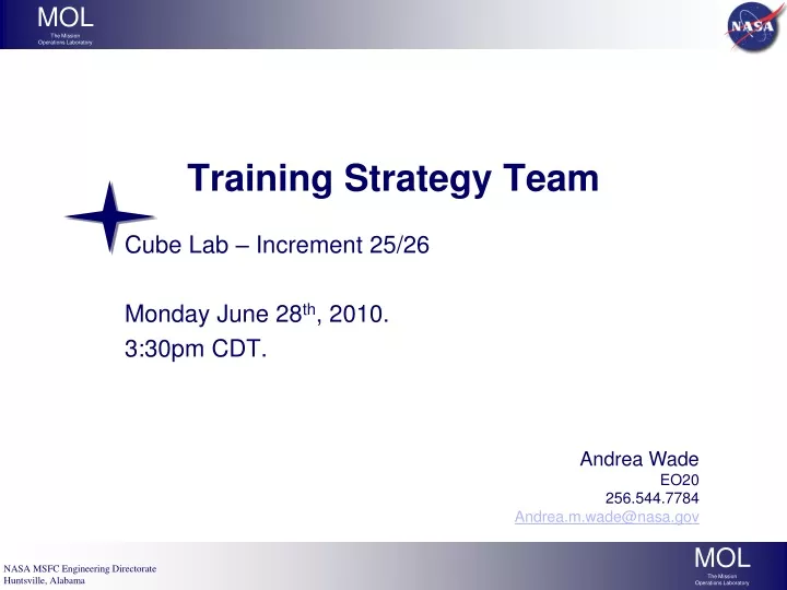
Training Strategy Team. Cube Lab – Increment 25/26 Monday June 28 th , 2010. 3:30pm CDT. Andrea Wade EO20 256.544.7784 Andrea.m.wade@nasa.gov. Agenda. Module Shipments this Increment Payload Hardware & Operations Description Crew Training Curriculum/Hours

E N D
Training Strategy Team Cube Lab – Increment 25/26 Monday June 28th, 2010. 3:30pm CDT. Andrea Wade EO20 256.544.7784 Andrea.m.wade@nasa.gov
Agenda • Module Shipments this Increment • Payload Hardware & Operations Description • Crew Training Curriculum/Hours • Proposed Payload Training Hardware (PD-Provided) • Proposed Payload Training Support Hardware (NASA-Provided) • On-Board Training Requirements/Development Flow • Payload Instructor Certification • Payload Training Data Set • Schedule
Module Shipments this Increment Inc. 25/26 Consists of the following flights with Cube Lab Modules… New Modules are going up on ULF6 (Module 7) and HTV-2 (Module 5, 9, and 10).
Module 7 • Ascent: ULF6 • Descent: 24S • Description: 2 LMA (Liquid Mixing Apparatus) trays transferred to ISS; already activated. LMA’s will be contained together in a Ziplock bag, and be housed in an inactive Cube Lab Frame until descent. • Operations: No data collection or proper Module Installation (aluminum Module remains on shuttle). Transfer operations only.
Module 5 • Ascent: HTV-2 • Descent: 24S • Description: A USB microscope, intended to be part of the Cube Lab facility and available for future Module experiments. • Operations: Remains in the Cube Lab Frame when not in use. After launch, microscope will undergone checkout activities (setup, checkout, stow). • 200 x 200 x 100 mm Aluminum box • 1 USB Microscope • 1 USB Camera and Cable • 1 Microscope Slide Kit (Note: all plastic slides)
Operation: Flex outer tubing to break inner ampoule cerium(III) nitrate hexahydrate solution Sodium hydroxide (0.5, 1, 2, 3M)solution Glass (completely contained) Ampoule Teflon Tube (Level 1) Bonded Teflon End Cap (Level 1) Bonded Teflon End Cap (Level 1) Polyolefin Shrink Tubing (Level 2) Heat Sealed Polyethylene Bag (Level 3) Module 9 • Ascent: HTV-2 • Descent: 24S • Description: A glow-stick experiment. Module contains mixing tube assemblies to be activated on-orbit. • Operations: Requires opening the Cube Lab Module and interfacing with the triple-containment system to break the glow-sticks (flex outer tubing to break inner tubing). This does not require any data transfers. • 100 x 100 x 100mm Aluminum box • Mixing tube assemblies housed in a block of foam.
Note: The Goretex vents permit gas exchange but contain the water. Outer Lexan Box (level 2) Goretex Vents 10 cc water bottle (Level 1) Plant Growth Chamber (Level 1) Electronics Sealed USB Type B connector USB Camera Figure 2: Cube Lab Module-10 Containment System Diagram Module 10 • Ascent: HTV-2 • Descent: 24S • Description: Plant growth experiment monitored by internal USB camera. • Operation: Self-contained experiment that should not require any deviation from existing Module Reconfig. and Data Collection activities. • 100 x 100 x 100mm Aluminum box • Electronics unit with a fluid container
Crew Training Curriculum and Hours • Module 7: No additional crew training needed. • Suggestion: Big Picture Words (because LMA trays will not be in the aluminum module container they saw in training). • Module 5: 0.5 hrs. (?) addition to “P Cube Ops 31165” • Objectives: update curriculum to include microscope setup, sample viewing, an stow. • Training Methodology: Hands-on • Training Tools: PD provides crew training hardware • How many crew members need to be trained? • Module 9: On-Board Training; 0.25 hrs. • Objectives: demonstrate for crewmembers how to open the module, “activate” the glow sticks, and restow them in the module. • Training Methodology: OCBT with a video. • Module 10: No additional crew training needed
PTU Proposal – PD Supplied Equipment PTU Proposal – JSC Supplied Equipment • PTC • RBA • Express Rack Simulator • Support Utilities • Power
On-Board Training • Could include Just-in-Time or Proficiency training that will be required prior to on-board payload operations. • Time for lessons is taken from Payload’s on-board operation allotment. • Planned OBT requirements are entered in the training data set, but not carried as payload training hrs. on the increment training plan. • CBTs must meet the template requirements of the On-Board Training Working Group. • All courseware used for training must have been through a payload training dry run. • OBT requirements must also be entered in the Planning Data Set (URC) so planning personnel can incorporate it in the timeline.
On-Board Training Development Process • A Lesson Concept Meeting is required (Ops Lead, Crew Office, PD) to finalize training objectives, lesson synopses, and planned OBT media. (we should cover most of this in the TST, and the rest can be coordinated via email). POH Vol.1 SOP 10.3OCBT DELIVERY FOR ELECTRONIC UPLINK 1. At approximately L-2 months, a PTDR is conducted on the final OCBT per SOP 10.5. Any deficiencies are corrected, and if necessary, a delta PTDR is held. 2. At L-1 month the User delivers the certified OCBT to the Ops Lead. 3. The Ops Lead posts the OCBT to the Training and Crew Operations web page and notifies the User and OBTWG Payload Rep of the posting via email. 4. Once the OCBT is posted, the User delivers the software validation document, virus signature verification, and OBTWG forms to the COSS Integration Group and either delivers the OCBT on a CD or notifies the COSS Integration Group of the URL where the OCBT is posted on the Training and Crew Operations web site. (Forms can be accessed at http://mod.jsc.nasa.gov/dt/obtwg/OBT_WG.htm and http://ranger.jsc.nasa.gov/DL2/S-poccb/sscdoc.shtml#validation ) JOIP NOTE: If the User delivers the OCBT to the COSS Integration Group on a CD, the label shall include at a minimum the TITLE, VERSION, DATE and a CONTACT NAME in a reasonable, legible format. 5. Once the COSS Integration Group completes their processing of the OCBT they notify the OBTWG Payload Rep. 6. Prior to each flight the OBTWG Payload Rep is responsible for notifying PAYCOM of any updates to the Crew Training Materials Real Time Tracking Matrix if changes are applicable to the flight (per POH volume 2, SOP 4.11).
Payload Training Data Set • Ops Lead will populate the TDS, with inputs from the PD • Baseline process • 1 ECR for training hardware updates (post-TST) • 1 ECR for curriculum updates (post-PTDR) Payload Instructor Certification • Mike Johnson certified for current “Cube Ops” course • Backup instructor needed? Or are we still good? • Who wants to be the voice actor for our Module 9 OBT video? • This person is also on the hook for the PTDR…
Training Development Milestones • Dataset Baseline – Simulator Hardware Date • Procedure Delivery & Chosen Author Date • Tabletop Procedure Review Date • Procedure Validation Date • Usability Test Date • Payload Simulator Test Procedure Date • Simulator Pre-Ship Test Date • Simulator Delivery Date • Simulator Post Ship Test Date • Lesson Plan/Courseware Delivery Date • PTDR Date • Dataset Baseline – Curriculum/Hours Date • Ready for Training Date
PTU Classes/Component Fidelities • Component Fidelities • Total Fidelity (T): All functional and physical characteristics representative of the flight design • Functional Fidelity (F): All functional characteristics representative of the flight design; physical characteristics are not represented • Physical Fidelity (P): All physical characteristics representative of flight design; functional characteristics are not required • Envelope Fidelity (E): Mockup with exterior shape and color representative of flight design • Visual Fidelity (V): No operational/functional capabilities; front panels representative of flight design