Download
1 / 37
390 likes | 596 Vues
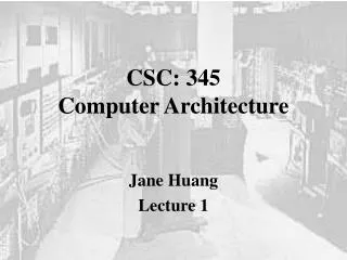
CSC 3650 Introduction to Computer Architecture. Spring 2011. Time: 3:30 to 6:30. Meeting Days: W. Location: Oxendine 1237B. Textbook : Essentials of Computer Architecture , Author: Douglas E. Comer, 2005, Pearson Prentice Hall. CPU Design. Dr. Chuck Lillie. Generic CPU State Diagram.

E N D
CSC 3650 Introduction to Computer Architecture Spring 2011 Time: 3:30 to 6:30 Meeting Days: W Location: Oxendine 1237B Textbook: Essentials of Computer Architecture, Author: Douglas E. Comer, 2005, Pearson Prentice Hall CPU Design Dr. Chuck Lillie
Generic CPU State Diagram • Fetch cycle: Fetch an instruction from memory, then go to the decode cycle. • Decode cycle: Decode the instruction – that is, determine which instruction has been fetched – then go to the execute cycle for that instruction. • Execute cycle; Execute the instruction, then go to the fetch cycle and fetch the next instruction.
Very Simple CPU • Access 64 bytes of memory • Each byte has 8 bits • Six bit address onoutput pins A[5..0] • Reads 8 bits from memory on inputs D[7..0] • CPU has on one programmer-accessable register, an 8-bit accumulator, AC
Very Simple CPU – Additional Registers • Six bit address register, AR • Six bit program counter, PC • Eight bit data register, DR • Two bit instruction register, IR
Very Simple CPU – Fetching Instructions from Memory • Send the address to memory by placing it on the address pins A[5..0] • After allowing memory enough time to perform its internal decoding and to retriwe ve the desired instruction, send a signal to memory so that it outputs the instruction on its output pins. • The address is stored in the program counter, PC FETCH1: AR PC • CPU asserts a READ signal and increments PC FETCH2: DR M, PC PC + 1 • Copy two high order bits of DR to IR and six low-order bits of DR to AR FETCH3: IR DR[7..6], AR DR[5..0]
Fetch Cycle for Very Simple CPU FETCH1: AR PC FETCH2: DR M, PC PC + 1 FETCH3: IR DR[7..6], AR DR[5..0]
Fetch and Decode Cycles for Very Simple CPU ADD1: DR M ADD2: AC AC + DR JMP1: PC DR[5..0] AND1: DR M AND2: AC AC ^ DR INC1: AC AC + 1
Complete State Diagram for Very Simple CPU This diagram includes the data paths for all the operations
Establishing Required Data Paths • Operations associated with each state of the CPU are: FETCH1: AR PC FETCH2: DR M, PC PC + 1 FETCH3: IR DR[7..6], AR DR[5..0] ADD1: DR M ADD2: AC AC + DR AND1: DR M AND2: AC AC ^ DR JMP1: PC DR[5..0] INC1: AC AC + 1
Establishing Required Data Paths • Regroup the operations, without regard for the cycles in which they occur, by registers whose contents they modify. AR: AR PC; AR DR[5..0] PC: PC PC + 1; PC DR[5..0] DR: DR M IR: IR DR[7..6] AC: AC AC + DR; AC AC ^ DR; AC AC + 1 • Connect every component to the system bus
Preliminary Register Section for the Very Simple CPU Simple Observations: AR only supplies its data to memory – don’t need to connect to any other component IR does not supply data to any other component via the internal bus – can remove output connection AC does not supply itws data to any component – remove connection to internal bus The bus is 8 bits wide, but not all data transfers are 8 bits (some are 6, some are 2) – need to specify which registers send and receive to and from which bus AC must be able to load the sum of AC and DR, logical AND of AC and DR. CPU needs to include an ALU to do that.
A Very Simple ALU Create separate hardware for each function and use a multiplexer to select the function results
Generic Hardwired Control Unit • Counter contains current state • Generates individual signals from current state • Logic to take individual state signals and generate control signals for each component, as well as the signals to control counter
Very Simple CPU has Nine States • Need four bit counter and a 4-to-16 bit decoder. Seven outputs of decoder will not be used • Assign FETCH1 to counter value 0 and use the CLR input of the counter to reach this state. • Assign sequential states to sequential counter values and use the INC input of the counter to traverse these states. CPU would assign FETCH2 to counter value 1 and FETCH3 to counter value 2, ADD1 and ADD2 to consecutive counter values as well as AND1 and AND2 • Assign the first state fo each execute routine based on the instruction opcodes and the maximum number of states in the execute routines. Use the opcodes to generate the data input to the counter and the LD input to the counter to reach the proper execute routine.
Relatively Simple CPU • Access 64K bytes of memory • Each byte 8 bits wide • Address pins A[15..0] • Bidirectional data pins D[7..0] • Programmer directly controls 3 registers • AC – 8 bit accumulator • R – 8 bit supplier of second operand • Z – one bit flag register set by arithmetic or logic operations
Fetch and Decode Cycles for Relatively Simple CPU FETCH1: AR PC FETCH2: DR M, PC PC PC + 1 FETCH3: IR DR, AR PC
Instructions JUMP1: DR M, AR AR + 1 JUMP2: TR DR, DR M JUMP3: PC DR, TR JMPZY1: DR M, AR AR + 1 JMPZY2: TR DR, DR M JMPZY3:PC DR, TR JMPZN1: PC PC + 1 JMPZN2: PC PC + 1 JPNZY1: DR M, AR AR + 1 JPNZY2: TR DR, DR M JPNZY3:PC DR, TR JPNZN1: PC PC + 1 JPNZN2: PC PC + 1 LDAC1: DR M, PC PC + 1, AR AR + 1 LDAC2: TR DR, DR M, PC PC + 1 LDAC3: AR DR, TR LDAC4: DR M LDAC5: AC DR STAC1: DR M, PC PC + 1, AR AR + 1 STAC2: R DR, DR M, PC PC + 1 STAC3: AR DR, TR SRTAC4: DR AC STAC5: M DR MVAC1: R AC MOVR1: AC R
Instructions ADD1: AC AC + R, IF (AC + R = 0) THEN Z 1 ELSE Z 0 SUB1: AC AC - R, IF (AC - R = 0) THEN Z 1 ELSE Z 0 INAC1: AC AC + R, IF (AC + R = 0) THEN Z 1 ELSE Z 0 CLAC1: AC 0, Z 1 AND1: AC AC ^ R, IF (AC ^ R = 0) THEN Z 1 ELSE Z 0 OR1: AC AC | R, IF (AC | R = 0) THEN Z 1 ELSE Z 0 XOR1: AC AC +| R, IF (AC +| R = 0) THEN Z 1 ELSE Z 0 NOT1: AC AC`IF (AC` = 0) THEN Z 1 ELSE Z 0
Establishing the Data Paths AR: AR PC; AR AR + 1; AR DR, TR PC: PC PC + 1; PC DR, TR DR: DR M, DR AC IR: IR DR R: R AC TR: TR DR AC: AC DR; AC R; AC AC + R; AC R; AC AC + 1; AC 0; AC AC ^ r; AC AC | r; AC AC +| R; AC AC` Z: Z 0 (both conditional)
Preliminary Register Selection for the Relatively Simple CPU Need modifications: AR and IR do not supply data to other components Pins D[7..0] are bidirectional, but cannot output data from pins in current configuration 16-bit bus not fully used by al registers. Must specifiy which bits of data bus are connected to which bits of registers Register Z not connected to anything
Designing the Relatively Simple CPU • Identify source of their operands • Identify all transfers that modify content of AC LDAC5: AC DR MOVR1: AC R ADD1: AC AC + R SUB1: AC AC - R INAC1: AC AC + R CLAC1: AC 0 AND1: AC AC ^ R OR1: AC AC | R XOR1: AC AC +| R NOT1: AC AC` LDAC5: AC BUS MOVR1: AC BUS ADD1: AC AC + BUS SUB1: AC AC - BUS INAC1: AC AC + 1 CLAC1: AC 0 • Rewrite as sum of two values and a carry LDAC5: AC 0 + BUS+ 0 MOVR1: AC 0 + BUS + 0 ADD1: AC AC + BUS + 0 SUB1: AC AC + BUS` + 1 INAC1: AC AC + 0 + 1 CLAC1: AC 0 + 0 + 0
Register Selection for the Relatively Simple CPU using Multiple Buses
Register Selection for the Relatively Simple CPU using Multiple Buses (cont)
Page 261, Problem 6.2