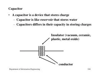
Download
1 / 9
100 likes | 281 Vues
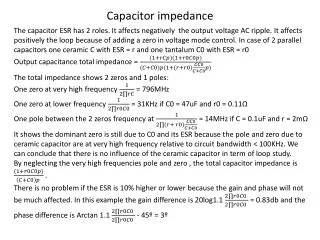
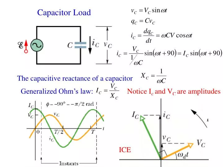
Capacitor Load. The capacitive reactance of a capacitor. Generalized Ohm’s law:. Notice I c and V C are amplitudes. ICE. Inductive Load. The Inductive reactance of a inductive. Generalized Ohm’s law:. Notice I L and V L are amplitudes. ELI. I. e. i. v R. V R. w t- f. V L. v C.

E N D
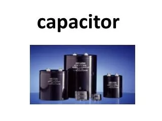
Capacitor Load The capacitive reactance of a capacitor Generalized Ohm’s law: Notice Ic and VC are amplitudes ICE
Inductive Load The Inductive reactance of a inductive Generalized Ohm’s law: Notice IL and VL are amplitudes ELI
I e i vR VR wt-f VL vC VC The series RLC circuit 1. Same current through R, L, C Same frequency as in the source 2. Consider VR, VC, VL
v V The series RLC circuit: Continuous Values at t. This relation has to be maintained as phosors are rotating • General rules: • KVL and KCL still hold, but values at the same t have to be used, i.e. vertical components in phasor diagram. • Vectors operation for Amplitude
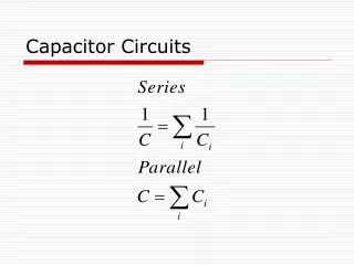
The series RLC circuit: Continuous =IZ =IR =I(XL-XC) Z is the impedance of the circuit
=IZ =IR =I(XL-XC) Examples 33-43P. A coil of inductance 88 mH and unknown resistance and a 0.94 mF are connected in series with an alternating emf of frequency 930 Hz. If the phase constant between the applied voltage and current is 75, what is the resistance of the coil. f=930 Hz wd=2pf
=IZ =IR =I(XL-XC) RLC Resonance XL>XC: inductive loading XL=XC: Resonance XC>XL: Capacitive loading
=IZ =IR =I(XL-XC) Conditions at Resonance • I is a maximum • Z is at minimum; Z=R; Z is purely resistive • XL=XC; inductive reactance cancels capacitive reactance; net reactance is zero • The phase angle is zero; the current is perfectly in phase with applied emf; the tangent of the phase angle is zero. • The driven frequency is identical to the natural frequency. • The power factor is unity