Download
1 / 37
370 likes | 521 Vues
Data Visualization. Lecture 4 Two Dimensional Scalar Visualization Part 2: Further Contouring and Other 2D Techniques. Return to Example. Consider this data:. -5. 10. 1. -2. Where does the zero level contour go? Can we draw a straight line which will approximate the contour line?. 10.

E N D
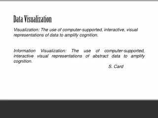
Data Visualization Lecture 4 Two Dimensional Scalar Visualization Part 2: Further Contouring and Other 2D Techniques
Return to Example • Consider this data: -5 10 1 -2 Where does the zero level contour go? Can we draw a straight line which will approximate the contour line?
10 -5 1 -2 Joining Intersections Directly • It is tempting to approximate by joining intersections with straight lines:
Ambiguity • But this does not always work - look at this data: 10 -5 -3 1 Try it - it is ambiguous!
10 -5 1 -2 What is the Problem? • The contour of the bilinear interpolant is NOT a straight line – it is a curve - Joining intersections with straight lines was only an approximation This is curve of:f(x,y) = (1-x)(1-y)f00+x(1-y)f10+(1-x)yf01+ xyf11 = 0 BUT how can we draw it?
-0.3 -0.3 Current point on contour Probes 0.9 0.9 Tracking Contours • We can track the contour in small steps through the grid rectangle - starting from the intersection with the edges • take a step, probe at an equal distance to either side, then predict next point; and so on Next point on contour BUT THIS IS SLOW!!
One technique – more efficient than tracking - is to split cell into four triangles Within a triangle, we can fit a linear model F(x,y) = a + bx +cy How do we split? How do we calculate a,b,c? What is the gain? f1 f2 f3 Solution by Decomposing Cell
Problem of drawing the curved lines has been circumvented by decomposing cell into four pieces within which the contours are well defined straight lines 0.75 Cell Decomposition -5 10 -3 1
As an alternative to decomposing the cell, we can try to understand how the curved contours of a bilinear interpolant behave The difficult case is: + - - + Avoiding Cell Decomposition Opposite vertices: two + and two - Where do the contour lines go?
A B + - - + - + - + Bilinear Interpolant • The bilinear interpolant has contours which are hyperbolas, and can be one of two forms: In each case there is a saddle point - if saddle point is -ve, then we have case A; if +ve, case B. Saddle point: fx=fy=0 .. Max in one direction, min in other
A + - - + A Possible Method • This suggests following method: • in ambiguous case, calculate saddle point and join intersection points according to how bilinear behaves: B - + - + saddle negative saddle positive Try it on the example earlier
Saddle Point • It is possible to calculate the saddle point in terms of vertex values (from fx = fy =0 ): • And the corresponding value: x = (f00 - f01 ) / D; y = (f00 - f10 ) / D D = f00 + f11 - f01 -f10 Saddle value = (f00f11 - f01f10)/D
-150 5 -1 100 Problem • In the ambiguous case, will the earlier four triangle method always give the same result as the saddle point method? Try this with both approaches
- + - + B Greater Accuracy • The greater understanding of the bilinear leads to a more accurate method • A single straight line approximation can be made more accurate by using two straight line pieces • see Lopes and Brodlie paper on Web site + - - + A
2D Interpolation - Scattered Data • Often the data will be given, not on a regular grid, but at scattered locations: f given at each marked point Approach: (i) triangulate (ii) build interpolant in each triangle (iii) draw contours
Triangulation • Triangulation is the process of forming a grid of triangles from the data points How can we construct the triangulation?
Tesselation • We solve the DUAL problem: • Suppose a wolf is stationed at each data point. Each wolf is equally powerful and dominates the territory closest to its own base • What are the territories dominated by each wolf?
Dirichlet Tesselation • The resulting tesselation is known as the Dirichlet or Voronoi tesselation • Given the Dirichlet tesselation for N points P1, P2, ... PN there is an algorithm for constructing the tesselation when an extra point is added
Point Q added Q Dirichlet Tesselation P2 Tesselation for P1, P2, P3 P3 P1
Dirichlet Tesselation P2 P3 P1 Q
Dirichlet Tesselation P2 P3 P1 Q
Dirichlet Tesselation • Determine polygon containing Q - here D3, surrounding P3 • Construct perpendicular bisector of P3Q and find intersection with D3 - this becomes point of modified tesselation • Determine adjacent polygon - here D2 • Repeat the above two steps until D3 is reached again, or there is no intersection • Remove all vertices and edges interior to the new polygon
Delaunay Triangulation P2 P3 P1 Q
Delaunay Triangulation • Triangulation formed by joining points whose ‘territories’ share a common boundary in the tesselation • This has the nice property that it avoids long skinny triangles • See the nice applets at: www.cs.cornell.edu/Info/People/chew/ Delaunay.html • Note the ‘empty circle’ property of the Delaunay triangulation
Contouring from Triangulated Data • The final step is to contour from the triangulated data • Easy – because contours of linear interpolant are straight lines – see earlier http://www.tecplot.com
Each vertex can be positive or negative (ignore zero for now) This gives 23 = 8 possible cases… … but there are only 2 distinct configurations No contour (all same sign) Contour (2 of one sign, 1 of the other) Implementation: Determine which of 8 cases Select code for the appropriate configuration f1 f1 f2 f2 f3 f3 Implementing Triangle-based Contouring All same sign Two same sign
For a rectangle, there will be 24 = 16 cases There are 4 configurations All same sign (no contour) 3 same sign (one contour piece) 2 adjacent with same sign (one contour piece) 2 opposite with same sign (two pieces, but ambiguous) + - + - + + + + + + - - + + - + Implementing Rectangle-based Contouring
Surface Views • A different mapping technique for 2D scalar data is the surface view. • Here a surface is created in 3D space, the height representing the scalar value • Construction is quite easy - suppose we have a rectangular grid
Constructing a Surface View - 2 Surface created as pair of triangles per grid rectangle. Rendering step is then display of triangles.
Examples - with added contours www.tecplot.com
Image Plots • A further mapping technique for 2D data is the image plot • There are three variants: • dot array : draw a dot at each data point, coloured according to the value (very fast, but low quality)
Image Plots Grid lines:
Image Plots Areas:
Cross Sections • Another option is to look at a cross-section through the data • For example, if x and y are the independent variables, we could fix y and look at f in terms of just x • then repeat for different y • this reduces the ES2 problem to a sequence of ES1 problems