Download
1 / 7
80 likes | 214 Vues
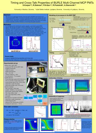
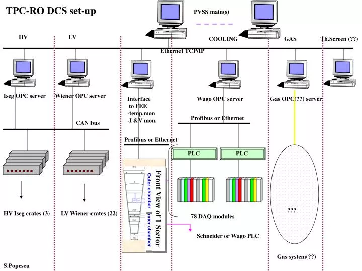
TPC-RO DCS set-up. PVSS main(s). PLC. PLC. HV. LV. COOLING. GAS. Th.Screen (??). Ethernet TCP/IP. Iseg OPC server. Wiener OPC server. Interface to FEE -temp.mon -I &V mon. Wago OPC server. Gas OPC(??) server. Profibus or Ethernet. CAN bus. Profibus or Ethernet. Outer chamber.

E N D
TPC-RO DCS set-up PVSS main(s) PLC PLC HV LV COOLING GAS Th.Screen (??) Ethernet TCP/IP Iseg OPC server Wiener OPC server Interface to FEE -temp.mon -I &V mon. Wago OPC server Gas OPC(??) server Profibus or Ethernet CAN bus Profibus or Ethernet Outer chamber FEC Front View of 1 Sector ??? HV Iseg crates (3) LV Wiener crates (22) 78 DAQ modules Inner chamber Schneider or Wago PLC Gas system(??) S.Popescu
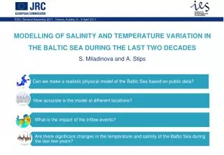
TPC Voltages DCS set-up PVSS main(s) HV LV Ethernet TCP/IP ECR optional optional Iseg OPC server(s) ?? Wiener OPC server(s) ?? 1 PCI-Can CRX CAN bus 18 nodes CAN bus 22 nodes • 22 LV PS crates (Wiener) • 5 modules/crate • 8 channels/module • Total: 880 channels 3HV PS crates (Iseg) 6 module/crate 16 channels/module Total: 288 channels PIT ~ 50 m ~ 50 m TPC detector TPC detector 1 PCI-Can S.Popescu
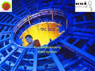
PVSS main(s) TPC COOLING DCS set-up Solution 1 ECR PLC1 PLC2 Ethernet TCP/IP Wago or Schneider OPC server CRX Ethernet TCP/IP Schneider or Wago PLC Profibus ADC(s) for T sensors Rack ~50 m ~50 m 1 node UX 1 node Flow Pressure module I/O Heaters Face1 9 + 1 nodes Flow Pressure module I/O Heaters Face2 9 + 1 nodes 9 nodes 9 nodes S.Popescu
PVSS main(s) TPC COOLING DCS set-up (Solution 2) ECR Ethernet TCP/IP OPC server Fieldbus card/driver (NI or Peak)… CRX Fieldbus CANopen ELMBs for T sensors ELMBs for T sensors Rack ~50 m ~50 m 1 node UX 1 node Flow Pressure module I/O Heaters Face1 Flow Pressure module I/O Heaters Face2 S.Popescu
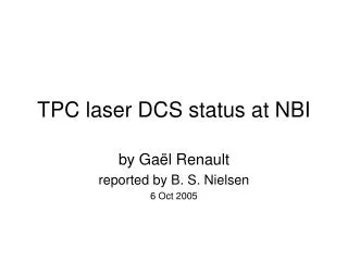
PVSS main(s) FEE DCS Monitor ECR Ethernet TCP/IP Ethernet TCP/IP FEE Control Application CRX Ethernet TCP/IP Or Profibus RCU RCU RCU RCU RCU RCU C6 : 20 FECs C5 : 20 FECs Outer chamber Parameters to be read/RCU: 25*(V1,V2,I1,I2, T) Error Register Parameters to be read/write: 25*(SW1, SW2) Total: ~ 45000 parameters C4 : 20 FECs FEC Front View of 1 Sector C3 : 18 FECs C2 : 25 FECs UX C1 : 18 FECs Inner chamber Control Link 6 RCU/sector Total: 216 RCU S.Popescu
Side 2 Reservoir Rack1 Rack2 Circ.pump ST/CV ALICE DCS TPC S.Popescu
Cooling Services from ST/CV ECR water water gas gas CRX TPC HMPID ITS SPD ITS SSD UX