Download
1 / 36
360 likes | 589 Vues
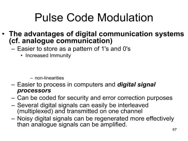
Modulation (Analogue). Modulation Modulation is a means by which some property of a signal is modified in order to encode data. See later examples, and Chapter 5 in book. Amplitude Modulation of an analog signal. Frequency Modulation. Phase Modulation. Sin(x+2 ) = Sin(x+4./2) = Sin(x).

E N D
Modulation (Analogue)
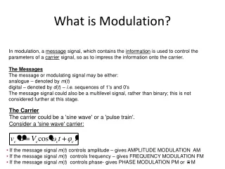
Modulation Modulation is a means by which some property of a signal is modified in order to encode data. See later examples, and Chapter 5 in book.
Phase Modulation Sin(x+2) = Sin(x+4./2) = Sin(x)
Phase Modulation PSK:Phase Shift Keying
Phase Modulation…2 bits/symbol In the 1st symbol time, there is an accumulated phase change of one right angle, 2 right angles in the 2nd, 2 right angles in the third, 3 right angles in the fourth, 4 right angles (or 0) in the fifth… Note that phase changes of 0 and 360 are indistinguishable, 90 and 450, etc The phase changes are [0, 1, 2, 3 ]* /2
In the diagram, there is a an accumulated phase change of 180 in the 1st symbol time, still 180 in the 2nd, 360 (or 0) in the 3rd, 360 in the 4th, 90 in the 5th, 90 in the 6th, 270 in 7th, 360 in 8th……There are 4 phase changes in total, 0, 1./2, 2./2, 3./2 8 QAM. In this diagram there are 4 phase changes, combined with 2 distinct amplitudes. Because there are a total of 8 identifiable line states, there are 3 bits per state.
Digital Modulation (Line Codes)
Desirable line code properties • Economical on bandwidth • No DC component • Inbuilt clock signal
The baud time is the time agreed between sender and receiver to indicate a given state of the line. In the example above there are two ‘symbols’, one to indicate the transmission of 1 bit, the other to indicate the transmission of a 0 bit. It is important that sender & receiver have the same notion of time.
Unipolar Has a DC component…undesirable.
In NRZ-I, A change of symbol is associated with the transmission of 1, while no change is associated with transmission of 0 (NRZ-I). This type of code is less demanding on bandwidth. (There are fewer state changes. A long sequence of zeros …synchronization problems.
Differential Manchester Encoding A change of symbol associated with 1. Repeat same symbol for 0
2B1Q code. There are 4 line states. There are 2 bits per symbol/state. If the line can support 8 separate states, then each state can carry 3 bits…. …..in general if the line can support 2n states, then each state carries n bits. The ‘Baud’ rate of a line means the rate at which a line changes State.
A Bipolar Code The AMI line code.(Alternate Mark Inversion). This is an example of a Bi-polar code. Notice that there are 3 line states. Used in ISDN. A long stream of zeros presents a problem of synchronization, i.eno transitions. Related codes are B6ZS, B8ZS (6 and 8 zero substitutions respectively) and HDB3.(High Density Bipolar, Order 3, substitutes for a stream of 4 consecutive zeros)
Multiplexing Time Division Multiplexing (TDM) Frequency Division Multiplexing (FDM) Wavelength Division Multiplexing (WDM) What is multiplexing?…. The Concurrent sharing of some resource for the sake of economy
FDM is reflected in the relation CostCosct = ½[Cos(c + )t + Cos(c - )t]. This relation shows how the baseband spectrum of a signal is translated to a new spectral location where it is centred on the modulating frequency c/2.
Digital Subscriber Loop (DSL) ‘Broadband’ • A technology used on the traditional copper wires of the telephone network to achieve high data rates typically for Internet access. • 2. There are a variety of DSL technologies, symmetric/asymmetric. ADSL is very common. More bandwidth is required in the downstream direction. Not suitable for business customers. Intended for residential use. • 3.The telephone system utilizes only a fraction of the entire bandwidth of the copper wires.i.e 4KHz . The entire bandwidth is approx 1Mhz or more, depending on the quality of the wires. DSL exploits the full Bandwidth. • 4. ADSL is an ANSI standard. It uses FDM to split the entire bandwidth of the wires into several bands. The lowest 25 KHz is reserved for telephone use (Only 4Khz is used, but the rest is used as a guard band to prevent interference between data and telephone traffic)
5.The remainder of the bandwidth is split into an upstream band and a downstream band, using e.g FDM. 6.Both the upstream and downstream bands are in turn split into several smaller channels using FDM. Each channel is used to carry data
Typically 225 channels will be defined in the downstream direction, each capable of carrying up to 60kbps. The DSL modem will initially probe each subchannel to discover the signal-to-noise ratio. It then assigns more bits to those channels which have the best S/N, less bits to channels with poorer S/N.