Download
1 / 49
490 likes | 625 Vues
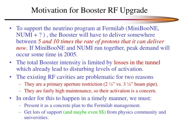
A Concept for Using the Digital Damper Board to Upgrade the Booster LLRF. Bill Foster June 12, 2003. Talk Outline. Motivation System Concept Options for Clock Domains Digital Phase Detector & PLL Radial Position Signal Notching & Multi-Batch Sync. 12 Step Plan. MOTIVATION

E N D
A Concept for Using the Digital Damper Board to Upgrade the Booster LLRF Bill Foster June 12, 2003 Concept for Booster LLRF - G. W. Foster
Talk Outline • Motivation • System Concept • Options for Clock Domains • Digital Phase Detector & PLL • Radial Position Signal • Notching & Multi-Batch Sync. • 12 Step Plan Concept for Booster LLRF - G. W. Foster
MOTIVATION Booster Low-Level RF. The Final Frontier. Concept for Booster LLRF - G. W. Foster
Booster Low-Level RF Concept for Booster LLRF - G. W. Foster
If something breaks… Ya Got Trouble :--Professor Harold Hill in “The Music Man” “Well, either you're closing your eyes To a situation you do not wish to acknowledgeOr you are not aware of the caliber of disaster indicatedBy the presence of a pool table in your community.Booster LLRF in your accelerator. Ya got trouble, my friend, right here, I say, trouble right here in River City… ...that’s Trouble with a capital T that rhymes with B…” Concept for Booster LLRF - G. W. Foster
SHIRLEY JONES AT ~25 Shirley Jones hit her prime in the 1960’s …much like the Booster. Concept for Booster LLRF - G. W. Foster
Shirley Jones in “The Partridge Family” Married to Jack Cassidy mother of David & Shaun Cassidy Concept for Booster LLRF - G. W. Foster
Booster LLRF External Connections • ~5 Inputs: • Wall-Current Monitor (Phase) • Transverse Pickup (RPOS) (BNL Uses two…) • Start Pulse (TCLK) • BDOT (Low bandwidth… replace w/lookup?) • MI AA Marker (Phase lock & notch cogging) • Two Outputs: Cavity A&B Drives • (Optional?) Beam Clock Output Concept for Booster LLRF - G. W. Foster
1. WCM 2. RPOS 5. MI RF 4. BDOT Notching and Cogging 3. TCLK A&B DRIVE OUT Concept for Booster LLRF - G. W. Foster
Generic Hardware Concept for Accelerator Instrumentation & Control 53 MHz, TCLK, MDAT,... Cables from Tunnel INPUTS: BPM Stripline Pickup Resistive Wall Flying Wire PMT RF Fanback Kicker Monitor …etc. FAST ADC Minimal Analog Filter Monster FPGA CPU Bus VME/ VXI/ PCI/ PMC etc. . . . . . . . . . FAST ADC Minimal Analog Filter ..OR.. NIM With Ethernet or FireWire OUTPUTS: Stripline Kicker RF Fanout Analog Monitor …etc. FAST DAC Concept for Booster LLRF - G. W. Foster
Damper With Frequency Sweep All Logic Inside FPGA FIFO needed due to phase shifts between DAC and ADC clocks as beam accelerates Concept for Booster LLRF - G. W. Foster
All-Coordinate Digital Damper 53 MHz, TCLK, MDAT,... 106 / 212 MHz Stripline Pickup FAST ADC Minimal Analog Filter Monster FPGA(s) 14 Transverse Dampers Identical X & Y FAST ADC Minimal Analog Filter Stripline Kicker Power Amp VME FAST DACs 2-10 > 27 MHz Resistive Wall Monitor FAST ADC Minimal Analog Filter Longi- tudinal (Z) Damper Broadband Cavity Power Amp FAST DACs 2-10 Concept for Booster LLRF - G. W. Foster
BPM FAST ADC Minimal Analog Filter 12 RPOS FAST ADC Minimal Analog Filter FAST DAC 12 FAST DAC FAST DAC “B” Drive “A” Drive Digital Booster LLRF Concept TCLK, 53 MHz, MI AA, MDAT,... ETHERNET [crystal] 400 MHz Monster FPGA DDS Beam Synched Clock 160-212 MHz (4x Booster RF) Wall Current Monitor (PHASE) FAST ADC Minimal Analog Filter 12 12 Concept for Booster LLRF - G. W. Foster
Echotek Card Used for Initial Dampers 105 MSPS AD6645 212 MHz DAC Daughter Card (S. Hansen/ PPD) • Echotek Board Originally Built to SLAC Design Specification • 65MHz DDC version to be used for RR BPM upgrade • 105 MHz version (with DAC “daughter card”) used for Dampers Concept for Booster LLRF - G. W. Foster
Butchering the Echotek Board • Scorched-Earth FPGA rewrite (GWF) • ~65 pages of firmware since Jan ‘03 • 212 MHz DAC “Daughtercard” • Sten Hansen & T. Wesson (PPD) • 3 channels for X,Y,Z • 212 MHz Output FIR (W. Schappert, RFI) • Pre-emphasis compensation for analog outputs • Prototype for 424 MHz output on final board • Input Buffer Amp/Splitter Box (Brian Fellenz,RFI) Concept for Booster LLRF - G. W. Foster
New Damper Board (A. Seminov) • SINGLE high-end FPGA (Altera Stratix EP1S25F672) • Four 212 MHz, 12-Bit ADCs (AD 9430) (With AD8369 VGA controlled by FPGA on input) • Four 424 MHz, 14-Bit DACs (TI DAC5675) • Digital Inputs: • TCLK, MDAT, BSYNCH, 53 MHz, Marker Pulse • Digital Outputs: • TTL, scope trigger, 1 GHz serial Links, firewire.. • Megabytes of Fast Memory (FIFOs & DSP RAM) • “NIM module” with Ethernet interface to ACNET Concept for Booster LLRF - G. W. Foster
This ADC can sample 53 MHz signals at 4 samples per RF cycle to measure both In-Phase and Quadrature on each cycle Concept for Booster LLRF - G. W. Foster
Digital Gain Control via FPGA Change gains “on the fly” or cycle-by-cycle Concept for Booster LLRF - G. W. Foster
Clock Domain Option #1:(being pursued at BNL – PAC’03) Single crystal ~212 MHz clocks everything. • Fixed Frequency ADCs & DACs, No Explicit PLLs • Asynchronous to Beam • Classical Digital Receiver for Phase Detector • Classical Direct Digital Synthesis of RF Outputs Concerns: - funny behavior as frequency sweeps? - lots of clock boundary crossings - approach does not naturally provide beam clock - bunch-by-bunch phase measurement difficult Concept for Booster LLRF - G. W. Foster
BNL PAC’03 BNL Switching from Digital Reciever Chip To FPGA Firmware Implementation Concept for Booster LLRF - G. W. Foster
BNL PAC’03 Concept for Booster LLRF - G. W. Foster
BNL PAC’03 Concept for Booster LLRF - G. W. Foster
BNL PAC’03 Concept for Booster LLRF - G. W. Foster
Clock Domain Option #2:(preferred) • Use one DAC Channel for Crystal-Controlled DDS of Beam-Synched RF Clock (38-53MHz) • The rest of circuit operates from this RF clock • Variable Frequency ADCs & DACs • Synchronous to Beam • Simple Implementation of Phase Detector & RF out • naturally provides beam clock • Few clock boundary crossings, simpler pipeline logic Concerns: - Tracking of PLLs on FPGA, ADCs, & DACs Concept for Booster LLRF - G. W. Foster
Q: What ADC Clock Speed is needed? A: 4x RF Bunch Frequency • Minimum needed for bunch-by-bunch Phase and Amplitude measurement • In frequency domain, 4x RF sampling measures bothin-phaseandquadrature components. • For Fermilab’s 53 MHz RF 212 MHz ADC’s Concept for Booster LLRF - G. W. Foster
212 MHz Sampling of RWM Pulse Low-pass Filter Spreads signal +/-5ns in time so it will not be missed by ADC Filter Reduces ADC Dynamic Range requirement, since spike does not have to be digitized Concept for Booster LLRF - G. W. Foster
Longitudinal Beam Instability in MI • Occurs with as few as 7 bunches (out of 588) • Prevents low emittance bunch coalescing and efficient Pbar bunch rotation • Driven by cavity wake fields within bunch train • Seeded by Booster & amplified near MI flat top. First Bunch ~ OK 7th Bunch Trashed Concept for Booster LLRF - G. W. Foster
Bunch-By-Bunch Phase vs. Turn NumberMeasured with MI Digital Damper • LLRF will Feed Back on Digital average of 84 Bunches • Damper Output derived from individual bunch phase errors Concept for Booster LLRF - G. W. Foster
Bunch-By-Bunch Intensity Concept for Booster LLRF - G. W. Foster
Radial Position (RPOS) • Use existing detector (RF Module) • Requires special RF clock out? • Low Digitization Bandwidth Required • Digitize BPM plates directly to get signal • More general approach • Less hardware • Choose which bunch(es) to feed back on • Gives a bunch-by-bunch signal for damper & diagnostics Concept for Booster LLRF - G. W. Foster
212 MHz Sampling of Stripline Signal Roles of “Phase” and “Amplitude” signals are reversed from unipolar case. Concept for Booster LLRF - G. W. Foster
Repetitive Waveform looks like simple sine wave, but contains bunch-by-bunch phase and amplitude “A - B” gives bunch-by-bunch “in-phase” signal “D - (C+E)/2” gives bunch-by-bunch “out-of-phase” or “quadrature” signal Vector Sum sqrt(I**2 +Q**2) is insensitive to clock jitter Concept for Booster LLRF - G. W. Foster
MAIN INJECTOR VERTICAL BPM (8 Bits) 1mm DIGITAL DAMPER POSITION SIGNAL (Batch Average) Concept for Booster LLRF - G. W. Foster
Single-Bunch BPM Measurement was tested by blowing out nearby bunches during Stacking Cycle Concept for Booster LLRF - G. W. Foster
BPM Resolution for 212 MHz Digitization of Single 53 MHz Bunch MAIN INJECTOR VERTICAL BPM (8 Bits) 1mm DIGITAL DAMPER POSITION FOR SINGLE 53 MHz BUNCH SINGLE-TURN (non-averaged) Concept for Booster LLRF - G. W. Foster
Bunch-By-Bunch Control RAM(in FPGA Firmware) • Bunch-by-bunch Damping Gain • Damping or Anti-Damping • Pinger with Programmable Tune, Timing… • Digital Random Noise Injected Into any Bunch Concept for Booster LLRF - G. W. Foster
Filter for Undamped, Damped, and Anti-Damped Bunches Concept for Booster LLRF - G. W. Foster
Blowing Selected Bunches out of the Machine (in X,Y, or both) …1110111001110001111… Neutrino Communications! Concept for Booster LLRF - G. W. Foster
ACNET CONTROLS • LLRF can behave differently on different cycles • Each control register becomes an ACNET Array Device indexed by MI State • Register contents switch automatically when MI State changes (D. Nicklaus) Concept for Booster LLRF - G. W. Foster
ACNET Control Devices (>250 total) • Master control registers & diagnostics are typically single devices • Configuration control registers are array devices indexed by MI State Concept for Booster LLRF - G. W. Foster
Adding a new ACNET Device 1) Add register(s) to FPGA Firmware Takes about 10 minutes from concept to Fast-Time Plot 2) Start Recompile (takes ~6 minutes) 3) Meanwhile, use DABBEL/D80 to define properties of new ACNET device 4) Download Firmware & Reboot Crate (~2 min.) Concept for Booster LLRF - G. W. Foster
So, What Problems are You Trying to Solve with this? • Reliability & Maintainability • Spares (incl. Hot spare for Experiments) • Cycle-By-Cycle Programmability • Notching & MI Synchronization • Digital Reproducibility • “Virtual Oscilloscope” on all signals • Documentation • Office Space! Concept for Booster LLRF - G. W. Foster