Download
1 / 40
420 likes | 689 Vues
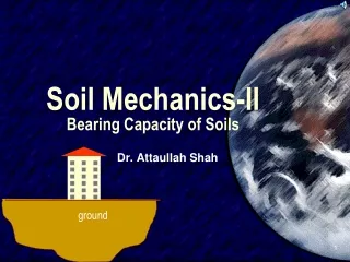
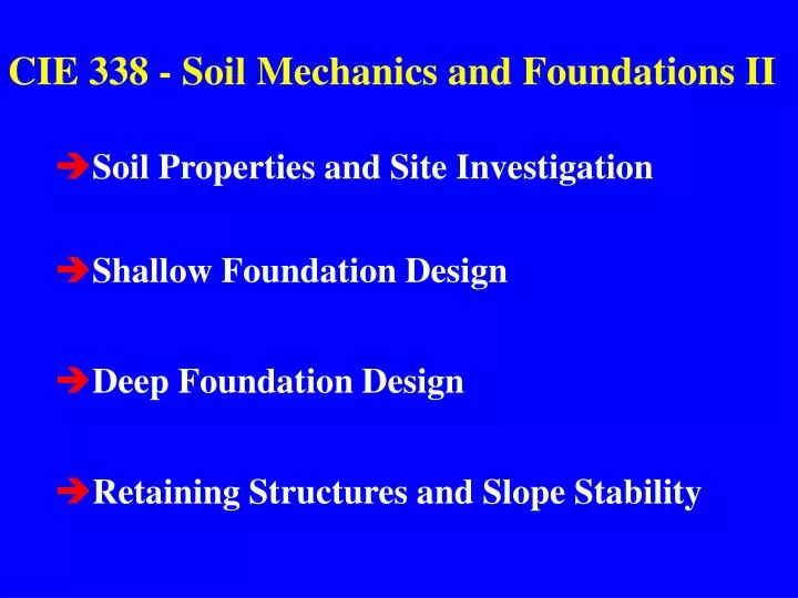
CIE 338 - Soil Mechanics and Foundations II. Soil Properties and Site Investigation Shallow Foundation Design Deep Foundation Design Retaining Structures and Slope Stability. Building Codes. Local and national codes guide practice. Design must conform to code or

E N D
CIE 338 - Soil Mechanics and Foundations II • Soil Properties and Site Investigation • Shallow Foundation Design • Deep Foundation Design • Retaining Structures and Slope Stability
Building Codes Local and national codes guide practice. Design must conform to code or Departures require approval Compliance does not assure safety or economy
P Column Ground Surface Df Footing B Shallow Foundation Df < 4B
A = total building foundation plan area Af = Individual footing area If Af => 0.5 A then consider a mat foundation
Column Loads Df Mat B Shallow (Mat) Foundation Df < 4B
Deep Foundation- Piles Friction Pile End Bearing Pile Hammer Hammer Hard Soil / Rock Firm Soil
Pile Shaft Hammer Poured in place fill Pre bored hole Deep Foundations
Foundation Df < 4B Df > 4B Shallow Deep Af < 0.5A Af > 0.5A Driven Cast in Place Footing Pile Shaft Mat Caisson Pier Bored Pile Af =sum of footing areas Df = depth of cover A = plan area of structure B = footing width
Earth Retaining Systems Wall System (external) Stabilized Earth System (internal)
Slope Stability How steep can the slope be? What is the factor of safety (FS)? How can we improve the FS?
Foundations transfer loads to subsurface DL - dead loads consist of the structure load usually well known LL - live loads are service loads, wind, earthquake usually involve large uncertainty
Types of Loads • Normal Loads, P • Shear Loads, V • Moment Loads, M • Torsion Loads, T (usually negligible)
z y
Normal load important for buildings P z y
Shear load important for retaining walls z Vy, Vx y Vy
Moment load important for retaining walls and buildings z Mx Mx, My y
Torsion load usually not significant z T y
Applied loads induce: Failure - (collapse/instability) Design with a generous factor of safety Movement - (settlement/deformation) Design to a performance criteria
Factor of Safety (FS) against failure or for bearing capacity FS = Resistance/Driving FS for buildings ~ 3 FS for retaining structures and slopes ~1.5
Movement / Settlement / Deformation Uniform settlement - least critical Even tilting - can be critical Distortion - potentially troublesome
s s As built foundation D
= maximum total settlement D= maximum differential settlement S = column spacing = distortion = D/ S Da = a * S a, denotes allowable
a = allowable rotation (Table 2.2, Coduto) Type of structurea Frame warehouse 1/200 Steel and reinforced concrete buildings 1/600 Unreinforced masonry 1/2500
Consult Fig. 2.9 and 2.10 (Coduto) Upper limit of D/ for foundations on sand = 1 Upper limit of D/ for foundations on clay ~ 0.3 The allowable total settlement is set to limit D
Example 2.1 A steel frame building without diagonal bracing S = 20 ft on clay foundation, what are the allowable total and differential settlements? Da = a * S obtain a = 1/500 (Table 2.2) Da = 0.5 in obtain D/ = 0.8 (Fig 2.9) a = Da * ( /D)= 0.5 / 0.8 = 0.6 in
Frost Heave Ground swell due to water volume expansion on freezing regular and < 50 mm (minor) Water rise by capillary action and formation of ice lenses irregular and of the order of 300 mm (major) Surface down thawing leads to super saturation foundation becomes very weak until drained
Conditions for Frost Heave Freezing temperatures usually natural, artificial also Source of water ground water table Frost susceptible soil (Table 2.3, Coduto) silts and fine sands - F4 soils
Measure to mitigate frost heave Insulate - rare Remove / replace - not common Place foundation below depth of heave, Df most common
Df is depth of frost penetration Varies by geographic location (Fig. 2.12, Coduto) Syracuse ~ 1.4 m Minnesota ~ 2.5 m California and Southern States < 0.3 m Consult local practice, building codes
Other water related problems Scour (armour, riprap) Corrosion (coating, cathodic protection) Sulfate attack (special cement, low w/c ratio) Decay, insects and fire (creosote pressure treat)
Soils 75 - 5 mm Gravel 5 - 0.075 Sand < 0.075 Silt and Clay Coarse #200 #200 Fine Grain size vs plasticity and liquid limit
mass volume Va Ma air voids Vw Mw water minerals Vs solids Ms Soil
Coarse grained soils e = void ratio = Vv/Vs emax and emin Dr = relative density = {(e-emin)/(emax-emin)}*100
Fine grained soils Water content = w = (Mw / Ms)*100 SL = shrinkage limit PL = plastic limit LL = liquid limit w = natural water content
Coarse grained soils emax e emin Fine grained soils w PL LL
Gravel Sand Silt Clay
Gravel Sand Silt Clay Gravity G Wellpoint V Wellpoint Electro-osmosis?