Download
1 / 42
420 likes | 509 Vues
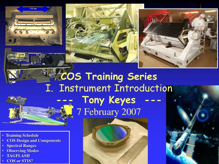
170 mm. COS Training Series Instrument Introduction --- Tony Keyes --- 7 February 2007. Training Schedule COS Design and Components Spectral Ranges Observing Modes TAGFLASH COS or STIS?. COS Training Schedule. Session 1: COS Instrument Introduction and Overview

E N D
170 mm • COS Training Series • Instrument Introduction • --- Tony Keyes --- • 7 February 2007 • Training Schedule • COS Design and Components • Spectral Ranges • Observing Modes • TAGFLASH • COS or STIS?
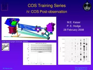
COS Training Schedule • Session 1: COS Instrument Introduction and Overview • Design characteristics, spectral elements, apertures, observing modes, sensitivities, resolutions, COS vs STIS, “TAGFLASH” • Session 2: Optimizing COS Observations I • Detectors, faint limits, backgrounds, optical design, BUFFER-TIME and buffer dump management, read-out charcteristics, pulse-heights, anomalies, internal calibrations • Session 3: Optimizing COS Observations I • Target acquisition, bright object issues • Session 4: COS Post-Observation • Pipeline, headers, keywords; calibration reference files and tables; reduced data products, formats
COS Science Design Requirements • Moderate Resolution (R~20,000) point-source UV spectroscopy; 0.1 arcsec pointing; 15 km/sec absolute (5 km/sec relative) radial velocity accuracy • Highest Possible Throughput • Maximize wavelength coverage per exposure
COS Design • Science Design Requirements met using a combination of HST capabilities • large collecting area • UV coatings • excellent pointing stability • superb image quality (after aberration correction); and • FUV: • single reflection system; fully corrected along dispersion, astigmatism perpendicular to dispersion • large format solar-blind cross delay line (XDL) detector • high-efficiency 1st-order holographic gratings • NUV: • FUV concept not available (no large format detectors) • STIS flight spare MAMA, fully aberration-corrected system, enhance wavelength coverage through use of three camera optics
COS Apertures • Apertures • Primary Science Aperture (PSA): 2.5 arcsec circular field stop • Bright Object Aperture (BOA): 2.5 arcsec + ND2 (~150x attenuation) circular field stop • Wavelength Calibration Aperture (WCA) • Flat Field Aperture (FFA)
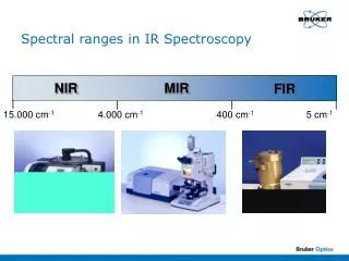
COS Optical Elements • Optical Elements (Gratings, Mirrors) • FUV: G130M, G160M, G140L • NUV: G185M, G225M, G285M, G230L, TA1 mirror (as MIRRORA and MIRRORB)
COS Detectors • FUV: Cross Delay Line (XDL) detector • windowless, CsI photocathode, MCPs feed XDL anode; photon counting • two 85 mm (dispersion-direction) x 10 mm segments (~9 mm gap between segments) • 2 x 16,384 x 1024 pixels; 6mm x 24mm pixel size (0.023 x 0.092 arcsec) • 6 pixels per resolution element (resel) along dispersion; 10 pixels per resel perpendicular to dispersion; (0.136 x 0.92 arcsec per resel) • Electronic “stim pulses” to characterize stretching and shifting in both coordinates (more robust than FUSE) • NUV: MAMA (STIS flight spare) • sealed CsTe photocathode; photon counting • 25 mm x 25 mm detector format (constrains optical design) • 1024 x 1024 pixels; 25mm x 25mm pixel size (0.024 x 0.024 arcsec) ; no subarrays • 3 x 3 pixels per resel (0.072 x 0.072 arcsec per resel) • opto-isolator problem fixed
170 mm COS Detectors – FUV XDL Top View
COS Detectors – NUV MAMA in the enclosure
COS Mechanisms External Shutter (STIS heritage) Aperture mechanism (translational motion in x and y perpendicular to beam) Optic Select Mechanisms 1 and 2 FUV Detector Door
Optics Select Mechanisms (OSM) OSM2 • Full 360 Degree Rotation • 101 arcsecond step size, with selectable step rate • User can specify minimum one-step movement via FP-POS command OSM1
COS Physical Characteristics Summary ** ** MAMA dark limits quoted are one-fourth of STIS values; actual dark rates TBD on-orbit
COS Optical Layout Calibration Platform 4 lamps, 3 beam splitters NCM3a, 3b, 3c (Focusing mirrors) NUV Detector (MAMA) NCM2 (Collimating mirror) FUV Detector Head (DVA) External Shutter (not shown) Aperture Mechanism positions 1 of 2 science and 2 calibration Apertures 2 degrees of freedom (x & y translation) Calibration Fold Mirror OSM2 positions 1 of 5 optics 1 degree of freedom (rotation) OSM1 positions 1 of 4 optics 2 degrees of freedom (rotation, focus)
FUV Detector Format • Remember: FUV detector has two segments (A and B)
FUV MCP (1 of 2 segments) NUV MAMA PtNe Wavecal External Science Internal PtNe Wavecal C B A C B A External Science COS Spectral Layout for Simultaneous Internal Wavecals and Science Spectra
Sample FUV PtNe Wavecal Spectrum Note: correct aspect ratio shown in lower panel --- graphic courtesy of COS IDT
Sample NUV PtNe Wavecal Spectra Single grating tilt yields 3 stripes G285M R ~ 20,000
COS Spectral Resolution (PSA*)and Bandpass Summary For BOA, wedge in ND filter degrades resolution by factor of ~2.5 for FUV modes and ~4 for NUV modes.
FUV Central Wavelengths and Wavelength Ranges per Segment Yellow text indicates default setting ** always used with SEGMENT A only
NUV Central Wavelengths Yellow text indicates default setting
A Word About FP-POS NOTE: For the FUV gratings, the lc are always separated by four OSM1 steps, so there is a continuous increment between FP-POS of adjacent central wavelength settings. This is not the case for the NUV gratings. • COS provides optional parameter FP-POS to perform dispersion-direction or wavelength dithers • One FP-POS step corresponds to the minimum movement (one step) of the OSM carrying the spectral element being used • For an exposure with any grating and lc, the observer may specify FP-POS = 1, 2, 3, 4, or AUTO (default is FP-POS=3) • AUTO corresponds to an automatic sequence of four separate exposures - that is, one at each FP-POS in the order FP-POS=1,2,3,4 • The central wavelength for any grating corresponds to FP-POS=3 (default) for that grating; the table gives the offset from lc in OSM steps for each allowed FP-POS
FUV Default Wavelength Ranges (FP-POS=3) • Note: G140L segment A records signal in “FUSE band” (l < l 100 Å ) } G140L } G160M } RED: Segment A G130M YELLOW: Segment B
Covering the (FUV) Gap • G130M and G160M: an 8 OSM1-step offset is required to bridge the segment A/B detector gap (any two non-adjacent lc settings at same FP-POS) • G130M: gap is ~17 Å; one FP-POS step ~2.3 Å; step between successive lc (e.g., 1309 to 1318) is ~9 Å • G160M: gap is ~21 Å; one FP-POS step ~2.9 Å; step between successive lc (e.g., 1600 to 1611) is ~11.6 Å
NUV Default Wavelength Ranges (FP-POS=3) G230L G285M G225M G185M A B C (this labeling for M modes only)
G285M #03285123358 G140L #03285101309 Spectral Drift • Optic Select Mechanism residual settling (“drift”) • Non-repeatable post-rotation motion measured in TV and ambient testing G160M #03285081037 Plateau Steep Rise Drift exceeds 1 resolution element Drift exceeds 1 resolution element
Spectral Drift Correction (TAGFLASH) • Correction needed to meet design requirements • Spectral resolution (and perhaps more importantly, line shape) • Wavelength zero point • TAGFLASH (FLASH=YES) will embed wavecals in science time • TIME-TAG mode ONLY; no correction for ACCUM • No overhead for wavecals at all • CALCOS corrects for drifts
Spectrum Drift Correction (TAGFLASH) • Analysis of thermal vac data shows image motion can be corrected to <0.25 resel/hr • FLASH=YES (TAGFLASH) now implemented as default observing mode for COS • Lamp is flashed at beginning and at intervals during every TIME-TAG exposure (based on time since last mechanism motion) • GO does not specify flash intervals or durations • Projected lamp usage sufficient to support COS over projected lifetime
Flash Characteristics and Monitoring • Flash Frequency (after major OSM move) • Always flash at start of exposure and at automatic intervals • First orbit following OSM move (4 flashes) • Flash at beginning exposure as reference • Intermediate flash early (after 600 sec) to follow fast drift • Intermediate flash after another ~1800 sec to follow change in drift slope • Flash every 2400 sec thereafter • If CVZ, then flash again after another 2400 sec, etc • Flash durations typically 5-10 seconds • SMOV and early Cycle 17 tests and monitoring planned • Determine drift character on-orbit for suite of OSM motions • Method allows changes for on-orbit understanding of drift • Early pattern is conservative (more flashes)
Important Modes/Parameters • TIME-TAG: position and time of each valid event are saved; pulse heights are recorded for FUV, but not NUV. Doppler correction is performed in the pipeline • default, highly recommended, for all targets less than 21,000 cts/sec; OK to 30,000 cts/sec with some continuity breaks (flux cal OK); requires BUFFER-TIME (time to fill one-half buffer or 2.3 million counts) [use ETC to estimate – details in Session 2] • ACCUM: each event increments memory location for recording pixel; only final accumulated image is saved. • 16384x128 (or 1024x1024) x 16 bits; for all count-rates > 30,000; justify for any other target • Pixel locations shifted on-board for orbital doppler correction • Important optional parameters: • FP-POS=1,2,3,4 or AUTO (either ACCUM or TIME-TAG) • FLASH=YES (TIME-TAG and PSA only; so-called TAGFLASH)
Target Acquisition Modes • ACQ/IMAGE • preferred option, “faint” targets; precise centering • ACQ/SEARCH • spiral-search; “bright” targets or poorer initial coordinates; moderate centering • ACQ/PEAKXD • cross-dispersion peakup • ACQ/PEAKD • long-dispersion peakup (must follow ACQ/PEAKXD) • Details in Session 3 Keyes (COS Training) – 7 February 2008 Slide 33 of xx
STIS or COS? COS is 10-30x faster than STIS in FUV at R=20,000 for point sources; even greater advantage at faint end due to low noise and pulse-height discrimination capability COS has quite degraded resolution for extended objects (see table below); for FUV, protions of objects closer than 1 arcsec apart will overlap; for NUV, spectrum stripes will partially overlap for objects more than 1 arcsec in spatial extent
COS or STIS? In NUV, COS M mode observing is inefficient for cases requiring large spectral coverage In NUV, COS background rate is expected to be 4x lower than STIS, but is TBD COS has no resolution higher than 20,000 and is a UV-only instrument COS FUV TIME-TAG mode includes the pulse-height for superior noise rejection STIS TIME-TAG has higher time-resolution and may be used on brighter targets The answer depends upon your application: refer to the IHBs and use the ETCs to evaluate your targets
Limiting Flux to achieve S/N=10 in 3600 sec exposures with uniform binning corresponding to R~20,000 (0.08 Å). COS PSA aperture used; STIS slit losses included.
Limiting Flux to achieve S/N=10 in 3600 sec exposures with uniform binning corresponding to R~20,000 (0.12 Å). COS PSA aperture used; STIS slit losses included.
COS Instrument Overview FUV Detector Electronics Box Cal Platform Main Electronics Box Remote Interface Unit NUV Detector 1750-3200A FUV Detector 1150-1775A Optics Select Mechanism–1 (G130, G140L, G160M, NCM1) Optics Select Mechanism–2 (G185M, G225M, G285M, G230L, TA1) Aperture Mechanism
Lamp Lifetime • Reduced lamp flash durations • G130M will be workhorse grating (longest lamp exposures) • But other gratings might be used with more OSM motions • e.g., extended NUV wavelength coverage • Assume 1000 COS orbits per year • Assume 4 flashes per orbit (4000 flashes per year, probably high) • Assume 15 seconds per flash • Assume 10 milli-amp current setting • On-orbit Usage • 8 amp hr lifetime budget per lamp (2 lamps available) • In one year, use 4 x 1000 x 0.01 x 15 / 3600 = 0.17 amp hr /yr • A 10 year mission => less than 2 amp hr of on-orbit usage => Lamp on-time should not be a lifetime issue