Download
1 / 15
160 likes | 182 Vues
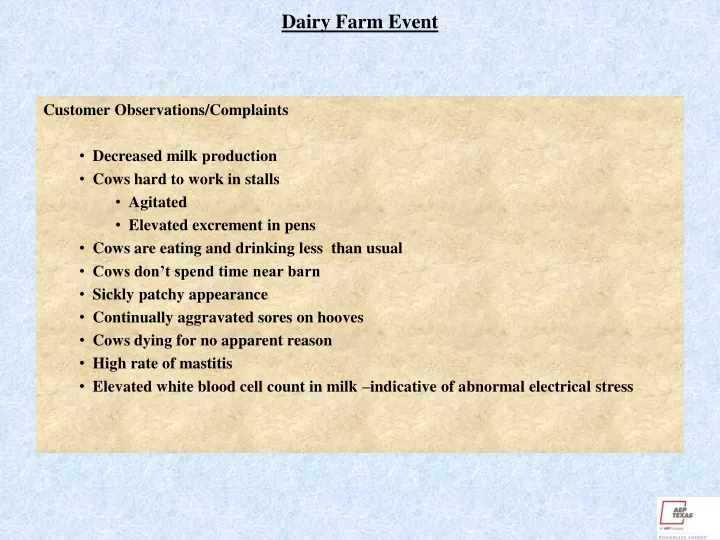
Dairy Farm Event. Customer Observations/Complaints Decreased milk production Cows hard to work in stalls Agitated Elevated excrement in pens Cows are eating and drinking less than usual Cows don’t spend time near barn Sickly patchy appearance Continually aggravated sores on hooves

E N D
Dairy Farm Event Customer Observations/Complaints • Decreased milk production • Cows hard to work in stalls • Agitated • Elevated excrement in pens • Cows are eating and drinking less than usual • Cows don’t spend time near barn • Sickly patchy appearance • Continually aggravated sores on hooves • Cows dying for no apparent reason • High rate of mastitis • Elevated white blood cell count in milk –indicative of abnormal electrical stress
Dairy Farm Event Findings, Causes, and Solutions 44 volts measured from milking equipment and various metallic items in the barn and house to ground. Breakers turned off, meter pulled – voltage persists. Discovered abandoned phone line with ground strap connected to slate house siding. Phone company removed line, voltage went to .3 volts or lower in all locations. 10 volts measured from window screen to ground Turned breaker in bedroom off and voltage went away. Found nail in romex. Farmer complained of being shocked in barn Found rebuilt compressor motor that was shorted to case. Ground wire was taped and not connected. Replaced motor and rewired properly - corrected problem. Farmer found 240 volts from breaker box to ground at adjacent oil field installation. Found shorted arrester and inadequate grounding – repaired by oil company. Remote ground monitor detected elevated voltage during bad weather Found elevated neutral current during fault events Installed isolation device between primary and secondary.
Burning Cow Event Facts • Cow was found at the bottom of AEP transformer pole, dead and burning. Cow was in contact with two pole grounds. • Transformer bank was connected wye – corner grounded delta. • No system neutral was present – only the three primary phase conductors were pulled to this location. • There were two pole grounds and ground rods on the transformer pole. One pole ground was connected to the secondary corner ground and the other was only connected to the tank ground of the transformers. • Other than capacitive coupling, there is no electrical connection between any of the transformer windings and the tank ground. • Service to 30 hp water pump is made via (150’) of # 2 quad. • Self contained three phase meter. • Three phase (480 volt) lightning arrester connected inside the meter base. • Ground rod at meter pole connected to secondary corner ground at the meter. • Customer disconnect box contains disconnect switches, fuses on all three phases, and overload/imbalance protection. No grounding present. Measurements & Observations at the time of the incident • Corner ground at transformer - >1500 ohms • Corner ground at meter pole – 29 ohms • Transformer pole had burned mark at ground level where the corner ground pole ground is attached to ground rod.
Burning Cow Event Calculations • Assumptions – 350 mA returning to transformer via ground rods (29 ohms), resistance of a cow – 500 ohms. • .35 amps x 29 ohms = 10.15 volts – voltage drop across ground system and the cow • 10.15 volts / 500 ohms = 20 mA – possible current through the cow. Conclusions: • The cow leaned against the pole ground and became a parallel path for load current. Since the resistance at the transformer pole was very high, the cow would have been the main current path via the pole ground. • Since the electrical system has been altered subsequent to the incident, measurements which duplicate the event cannot be made. However, the measurements which were made indicate a possibility of in excess of 20 mA passing through the cow. • 15 mA causes breathing difficulty in humans and 35 mA caused fibrillation. • The cow very likely became incapacitated on contact and fell into the pole ground. Continued contact caused heating and burning over an extended period of time. • Some publications say that a cow can actually have as low as 225 ohm resistance. This would double the calculated amperage flowing through the cow.
Burning Cow Event Possible Causes • High impedance ground connection at the transformer pole • No ground molding present giving access to the bare ground conductor. • Possible bad connections on the current carrying conductors (insulinks, and crimpets). This would cause more return current to use an alternate path back to the source (transformer secondary). • Possible lightning arrester conduction causing raised current level in grounding system. • Possible partially grounded motor winding or conductor in the well. Corrective Measures • Ensure good ground rod installation and connections to pole ground. • Install ground molding. • Make sure all conductor connections are well installed and of low impedance. • Customer fuse on corner grounded leg is against code and could cause excessive ground currents if is blows. Since the customer secondary is not grounded as it should be by code, this is not as big an issue as it would be if the customer’s electrical system were wired to NEC.
Burning Cow Event Other Observations: • The voltages and currents impressed on the grounding system due to normal load currents is directly proportional to the relative impedances of the return paths to the source. All conductors connected to the source, whether grounded or not, will carry load current. In normal operation, the impedance of the current carrying conductors (triplex or quad) is much lower than the impedance of the grounding system. In addition, the grounding system is generally much lower impedance than anything which might come into contact with a pole ground. This means that under normal operating conditions, only a very small portion of the load current returns through the grounding system and a much smaller portion of that will pass through a person or animal coming into contact with the grounding system. However, the following conditions can cause a hazard to those contacting the grounding system: • High impedance of normal current carrying conductors/connections. • High impedance of grounding connections. • Abnormally high currents. • It should be noted these conditions are not limited to corner grounded systems. A more typical center grounded 120/240 volt connected system is as likely to present the same hazard as a corner grounded system if the same conditions are present. In general however, there is a system neutral present and multiple pole grounds and ground rods on the AEP distribution system. These multiple connections have the effect of lowering the overall ground impedance and providing many low impedance (in relation to persons) paths for load or fault current.
Damaged Water Pipe Event Event Facts: • 69 KV phase conductor broke and fell to the ground creating a high impedance fault. • Electromechanical relays failed to operate substation breakers on either end of line. • Fault continued for several minutes until remote overcurrent relays picked up and tripped the circuit open. • Different durations from each end. • (6500’) of wood pole construction without a tie from pole ground to the static. • (6000’) of lattice steel structure construction with bonds to the static. • Soil type in the area between the fault and the affected residence is more conductive than in the surrounding are • Copper water pipes in the walls of two residences were damaged. The damage at one of the residences was catastrophic. • Telephone drops to the residences were burned off at the service entrance. • Water pump controls were burned up.
General Remediation Measures for Stray Voltage Primary System: • Reduce primary neutral currents • Balance loading on the primary system • Maintain capacitor banks • Reduce Resistance to Neutral Currents • Replace high impedance connections (bolted, twisted) • No reduced neutral for new construction • Improve Grounding • More driven ground rods and pole grounds • Don’t forget ground molding • Eliminate the source of phase to ground faults • Trim trees • Shorter spans • Continual inspection and maintenance