Download
1 / 26
260 likes | 441 Vues
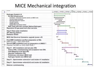
3rd meeting on GTK electro-mechanical integration. OUTLINE. Vessel dimensions GTK assembly carrier Electrical connections Cooling pipes integration Vessel alignment with the beam Next steps Conclusion. Vacuum Vessel. Vacuum Vessel. Vessel 3D (GTK 1+2) drawing .

E N D
OUTLINE Vessel dimensions GTK assembly carrier Electrical connections Cooling pipes integration Vessel alignment with the beam Next steps Conclusion 3rd meeting on electro-mechanical integration M.Morel
Vacuum Vessel 3rd meeting on electro-mechanical integration M.Morel
Vacuum Vessel Vessel 3D (GTK 1+2) drawing . 3rd meeting on electro-mechanical integration M.Morel
GTK assembly carrier 3rd meeting on electro-mechanical integration M.Morel
Integration of 10 Readout chips + Sensor with the Cooling Wafer Reference #1 Sensor First bond pad of 2 Readout chip could be used as references to precisely glue the sensor assembly on the cooling wafer. Readout chip Cooling Wafer Reference #2 3rd meeting on electro-mechanical integration M.Morel
Gluing Readout chips on the cooling Wafer Sensor Special attention has to be taken to avoid an overflowing of glue to the readout chips pad and bump bonds. Readout chip Cooling Wafer 3rd meeting on electro-mechanical integration M.Morel
GTK assembly carrier Top view Bottom view 3rd meeting on electro-mechanical integration M.Morel
Vessel & Carrier board outside View 3rd meeting on electro-mechanical integration M.Morel
CARRIER BOARD SUPPORT The aluminium support will be glued on the carrier board. Vacuum tightness will be assure with an o-ring joint. O-ringemplacement 3rd meeting on electro-mechanical integration M.Morel
Mechanical guides used during GTK carrier insertion in the Vessel. 3rd meeting on electro-mechanical integration M.Morel
Mechanical guides 2 other rails will guide the GTK carrier inside the vessel. 3rd meeting on electro-mechanical integration M.Morel
Electrical connections to the GTK carrier 3rd meeting on electro-mechanical integration M.Morel
GTK carrier specifications !! High frequency lines between The readout chips and optical transmitter modules. µ via technology board is foreseen. High current in the power supplies (25A) 3rd meeting on electro-mechanical integration M.Morel
Cross section representation 3rd meeting on electro-mechanical integration M.Morel
Bonding representation between GTK carrier and a Readout chip Signals Layer 2V5A 2V5 1V2 Fist possibility: This staircase carrier allows full planes for the power supplies. GND 3rd meeting on electro-mechanical integration M.Morel
Bonding representation between GTK carrier and a Readout chip Second possibility: Pin to pin bonding 3rd meeting on electro-mechanical integration M.Morel
Bonding representation between GTK carrier and a Readout chip Signals 2V5 1V2 GND Third possibility: Power supplies on bus 3rd meeting on electro-mechanical integration M.Morel
Cooling pipe integration 3rd meeting on electro-mechanical integration M.Morel
First possibility: Integration of the cooling pipe in the GTK carrier board Nano port Cooling pipe input connector Cooling Wafer 3rd meeting on electro-mechanical integration M.Morel
Second possibility: using the Aluminium support with a pressure-tight connector Cooling pipe input connector 3rd meeting on electro-mechanical integration M.Morel
GTK Vessel&BeamPositioning 3rd meeting on electro-mechanical integration M.Morel
GTK Vessel and XZ table Connections with the beam pipe could be made using a bellows (Tombac) to insure enough length and low stress. 3rd meeting on electro-mechanical integration M.Morel
Next steps • Design & construct vessel prototype • Study, design & construction of assembly carrier prototype • (PCB) • Mechanical dimensions • Signal integrity (6 Gbit/s per chip) • Signal length • Routing density • Wire bonding optimization • Straight wire bonds • Vacuum tightness • Start study to make design compatible with vessel cooling option 3rd meeting on electro-mechanical integration M.Morel
Conclusion • Definition of specification started • GTK3 needs more definition • Integration proposal worked out • Prototyping research & design can start 3rd meeting on electro-mechanical integration M.Morel