Download
1 / 21
210 likes | 360 Vues
Lecture 6 Introduction to Pipelining. B. C. D. A. Pipelining: Its Natural!. Laundry Example Ann, Brian, Cathy, Dave each have one load of clothes to wash, dry, and fold. Washer takes 30 minutes. Dryer takes 40 minutes. Folder takes 20 minutes. Time. 6 PM. Midnight. 7.

E N D
Lecture 6Introduction to Pipelining CS510 Computer Architectures
B C D A Pipelining: Its Natural! Laundry Example • Ann, Brian, Cathy, Dave each have one load of clothes to wash, dry, and fold • Washer takes 30 minutes • Dryer takes 40 minutes • Folder takes 20 minutes CS510 Computer Architectures
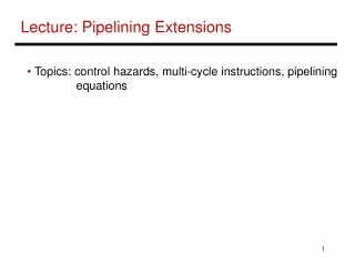
Time 6 PM Midnight 7 8 9 11 10 40 20 30 40 20 30 40 20 30 40 20 30 90 A 90 B 90 C 90 D Sequential laundry takes 6 hours for 4 loads Sequential Laundry T a s k O r d e r If they learned pipelining, how long would laundry take? CS510 Computer Architectures
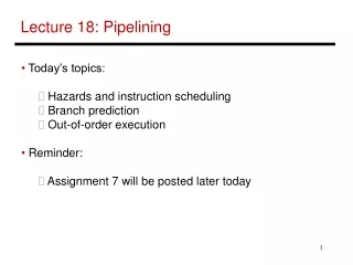
6 PM Midnight 7 8 9 11 10 Time 30 40 40 40 40 20 90 T a s k O r d e r A 90 B 90 C 90 D Pipelined laundry takes 3.5 hours for 4 loads Pipelined LaundryStart Work ASAP CS510 Computer Architectures
6 PM 7 8 9 Time 30 40 40 40 40 20 A T a s k O r d e r B Draining Filling C D Pipelining Lessons • Pipelining doesn’t help latency of single task, it helps throughputof entire workload • Pipeline rate is limited by the slowest pipeline stage • Multiple tasks operating simultaneously • Potential speedup = Number pipe stages • Unbalanced lengths of pipe stages reduce speedup • Time to “fill”pipeline and time to “drain” it reduces speedup CS510 Computer Architectures
DLX Instructions Instruction type/ Instruction meaning Opcode Data transfers Only memory address mode is 16-bit disp + contents of a GPR LB, LBU, SB Load byte, load byte unsigned, store byte LH, LHU, SH Half word LW, SW Word(to/from integer registers) LF, LD, SF, SD Load SP float, load DP float, store SP float, store DP float MOVI2S, MOVS2I Move from/to GPR to/from a special register MOVF, MOVD Copy one FP register or a DP pair to another register or pair MOVFP2I, MOVI2FP Move 32 bits from/to FP registers to/from integer registers Arithmetic/logical ADD, ADDI, ADDU, ADDUI Add, add immediate(16 bits); signed and unsigned SUB, SUBI, SUBU, SUBUI Subtract MULT, MULTU, DIV, DIVU Multiply and divide, signed and unsigned; operands must be FP regs; all operations take and yield 32-bit values AND, ANDI And, and immediate OR, ORI, XOR, XORI OR, Exclusive-OR LHI Load high immediate --- load upper half of register with immediate CS510 Computer Architectures
DLX instructions Shift SLL, SRL, SRA, SLLI, Shifts: both immediate(S__I) and variable form (S__); logical, arithmetic SRLI, SRAI S__, S__I Set conditional: “__” may be LT, GT, LE, GE, EQ, NE ControlConditional branches and jumps; PC-relative or through register BEQZ, BNEZ Branch GPR equal/not equal to zero: 16-bit offset from PC+4 BFPT, BFPF Test comparison bit in the FP status register and branch; 16-bit offset J, JR Jumps:26-bit offset or target in register JAL, JALR Jump and link: save PC+4 in R31 TRAP Transfer to operating system at a vectored address RFE Return to user code from an exception; restore user mode Floating pointFP operations on DP and SP format FcnD, FcnF Fcn: ADD, SUB, MULT, DIV CVTF2D, CVTF2I, Convert instructions: F single precision, D double precision, I integer CVTD2F, CVTD2I, Both operands are FPRs CVTI2F, CVTI2D, __D, __F DP and SP compares: “__” = LT, GT, LE, GE, EQ, NE; sets bits in FP status register CS510 Computer Architectures
I - type instruction 5 5 6 16 Opcode rs1 rd Immediate Loads, stores, all immediates, conditional branches, Jump register, jump and link reg R - type instruction 5 5 5 6 11 Opcode rs1 rd rs2 func Register-register ALU operations: Func - Add, Sub,... J - type instruction 6 26 Opcode Offset added to PC Jump and Jump and link, trap and return from exception DLX Instruction Format CS510 Computer Architectures
Add NPC +4 PC Instr. Memory IR 5 Steps of DLX Instr. Execution:Step1 Step 1: Instruction fetch cycle (IF) • Read instruction from memory and store into IR • IR ¬ Mem[PC] • Calculate the next instruction address • NPC ¬ PC+4 • 1 instruction is stored in consecutive 4 bytes CS510 Computer Architectures
A Reg File IR B Rd b OP Sign Ext Imm 32 16 5 Steps of DLX Instr. Execution:Step2 • Step 2: Instruction decode/register fetch cycle (ID) • Read source registers to A and B • A ¬ Regs[IR6..10] • B ¬ Regs[IR11..15] • Make 16 bits sign extension of 16-bit immediate field to make a 32-bit immediate value Imm ¬ ((IR16)16## IR16..31) • Decoding is done in parallel: fixed-field decoding b ¬ Rd CS510 Computer Architectures
5 Steps of DLX Instr. Execution:Step 3 • Step 3: Execution/effective address cycle (EX): • Memory reference: Effective Address calculation • ALUOutput ¬A + Imm • Register-register ALU instruction: Perform ALU operation with R’s • ALUOutput ¬ A func B; func B • Register-Immediate ALU instruction: Perform ALU operation with immediate operand • ALUOutput ¬ A op Imm • Branch: Effective Address calculation for branch target address • Determine condition code • ALUOutput ¬ NPC + Imm; Cond ¬ (A op 0) CS510 Computer Architectures
Zero? Cond NPC MUX A ALUOut ALU B MUX Imm OP Step 3 EX CS510 Computer Architectures
NPC MUX PC ALUOut Cond Data Memory LMD B 5 Steps of DLX Instr. Execution:Step 4 Step 4: Memory access/branch completion cycle (MEM): • Memory reference : Access memory either • for LD: LMD ¬ Mem[ALUOutput] or • for ST: Mem[ALUOutput] ¬ B • Branch : Test Condition • if (cond) PC ¬ ALUOutput, else PC ¬ NPC; CS510 Computer Architectures
LMD MUX Register File ALUOut OP 5 Steps of DLX Instr. Execution:Step 5 • Step 5: Write-back cycle (WB): • Reg-Reg ALU : Store the result into the destination register • Regs[IR16..20] ¬ ALUOutput; • Reg-Immediate ALU : Store the result into destination register • Regs[IR11..15] ¬ ALUOutput; • Load instruction: Store the data read from memory to the destination register • Regs[IR11..15] ¬ LMD; CS510 Computer Architectures
WB Stage ID Stage EX Stage MEM Stage IF Stage MUX Add Zero? +4 MUX ALU Output Data Memory PC Instr. Memory Reg File ALU LMD MUX MUX SMD Sign Ext 32 16 5 Steps of DLX Datapath CS510 Computer Architectures
MR-instructions A Simple Implementation • A multi-cycle implementation • needs temporary registers-- NPC, IC, A, B, Imm, Cond, ALUOutput, LMD • CPI improvements: Branch - 4 cycles, ALU - 4 cycles • if brach freq : 12 %, ALU instr. freq : 44% CPI = 0.12 x 4 + 0.44 x 4 + 0.44 x 5 = 4.44 • A single-cycle implementation • one long clock cycle • very inefficient for most machines that have a reasonable variation among the amount of work • requires the duplication of FU that could be shared in a multi-cycle implementation CS510 Computer Architectures
Time(clock cycles) CC1 CC2 CC3 CC4 CC5 CC6 CC7 CC8 CC9 ALU DM Reg Reg IM Instruction Order ALU Draining DM Reg Reg IM ALU DM Reg Reg IM ALU DM Reg Reg IM Filling ALU DM Reg Reg IM Visualizing Pipeline CS510 Computer Architectures
Saving Information Produced by Each Stage of Pipeline • Information need to be stored at the end of a clock cycle, otherwise it will be lost • Each pipeline stage produces information(data, address, and control) at the end of the clock cycle • Thus, we need a storage(called inter-stage buffer) at end of each pipeline stage CS510 Computer Architectures
Inter-Stage Buffer in DLX Pipeline • F/D Buffer • IR, NPC • D/A Buffer • A, B, Imm, b(destination Reg address to store result), OP(OP-code), cond • NPC • A/M Buffer • ALUout(arithmetic result or effective address) • NPC, cond, b, OP • M/W Buffer • LMD(data for LD) • ALUout(arithmetic result), b, OP CS510 Computer Architectures
WB Stage ID Stage EX Stage MEM Stage IF Stage MUX Add Zero? +4 MUX M/W Buffer F/D Buffer F/D Buffer D/A Buffer A/M Buffer Data Memory PC Instr. Memory Reg File ALU LMD MUX MUX SMD Sign Ext 16 32 Pipelined DLX Datapath- Multicycle - CS510 Computer Architectures
Reminder • In conventional Single Port Memory, Instruction Memory and Data Memory are the same memory • Both IF and Mem stages use memory • One instruction uses the same hardware resource in two different cycles • Two instructions try to use the same hardware resource in different stages of pipeline at the same time • For Branch instructions, Branch Target Address is available in the Mem stage CS510 Computer Architectures