Download
1 / 28
280 likes | 449 Vues
Erik Mueller Michael White. Microthruster Test Platform Design Presentation II. Contents. Introduction Problem Solution Sensing Frame Testing Q&A Sources. Microthrusters. Microthrusters produce <1N of thrust ( mN range) Various propulsion systems (standard, mono, ion drive).

E N D
Erik Mueller Michael White Microthruster Test PlatformDesign Presentation II
Contents • Introduction • Problem • Solution • Sensing • Frame • Testing • Q&A • Sources
Microthrusters • Microthrusters produce <1N of thrust (mN range) • Various propulsion systems (standard, mono, ion drive)
The Problem • Thruster and forces involved are minute • Must be rugged and durable • Modular design preferable
Our Solution • Sensing is done through direct thrust measurement using a strain gauge sensor. • Thruster assembly is suspended atop a pole • Secondary force measurement using indirect thrust plume measurement.
System Overview Indirect Thrust Plume Pendulum Sensor FM Modulator Circuit Fire Control Strain Gauge Amplifier Circuit DAQ Lab View Software
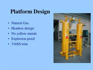
Frame • Single pole for the thruster support, grooved bracket w/ clamping system. • Material likely to be aluminum • Easy to work with compared to steel • Strength is more than adequate for the forces involved
Direct Force Measurement • Strain Gauge • Load Cell • Signal Amplification
Indirect Thrust Measurement • Capacitive Plate System • Exhaust plume exerts force on a plate Induced Force Thruster
Capacitive Pendulum • Uses electronic principle of capacitance • Needle point fulcrums eliminate frictional losses • Double pendulum plates eliminate mechanical noise
Signal Processing • Series of amplifiers and filters used to measure the change in signal
Signal Processing • Alternatively, use an FM generator per plate • Compare frequency shifts to determine deflection. • Advantage – more resistant to noise and distortion • Disadvantage – potentially more complex
Software • The signal processor will tie into a computer, along with the rocket ignition circuitry. • Both subsystems will be integrated into a single user-controlled program. We are considering Labview at this time.
Testing • One rocket test scheduled in the coming weeks to gauge ignition methods & rocket plume • Subsequent test once strain subsystem complete. • Currently creating and testing software with a load-cell.
Work Breakdown Structure • Week 5-6 Subsystem and structure prototype • Week 6-7 Electrical circuit schematics • Week 5-9 Software composition and test • Week 7-10 Final mechanical component fabrication & revision • Week 9-12 Assembly, testing, revisions if needed • More details on website
Works Cited • http://www.grc.nasa.gov • http://images.machinedesign.com • www.answers.com/topic/piezoelectricity • http://www.boeing.com/defense-space/space/bss/factsheets/xips/xips.html • Traceable calibration of the 3-axis thrust vector in the millinewton range, EB Hughes and S Oldfield, National Physical Laboratory • Direct Thrust Measurement of In-FEEP Clusters, IEPC-2005-235, K. Marhold and M. Tajmar, ARC Seibersdorf research GmbH • Rocket Thrust Measurement For an Estes B6-2 Model Rocket Engine, Peter Hyatt, Jeremy LeFevre, Russell Dibb, Bringham Young University • Thrust stand for ground tests of solid propellant microthrusters, S. Orieux and C. Rossi and D. Esteve, Review of Scientific Instruments, Volume73, Number 7, July 2002 • A Ground Test Rocket Thrust Measurement System, Mary Fran Desrochers, Gary W. Olsen, M. K. Hudson, Department of Applied Science and the Graduate Institute of Technology, University of Arkansas • MilliNewton Thrust Stand Calibration Using Electrostatic Fins, Allen H. Yan, Bradley C. Appel, Jacob G. Gedrimas, Purdue University