Download
1 / 57
600 likes | 666 Vues
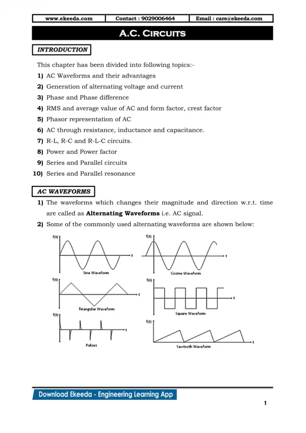
AC Circuits and Resonance Conclusion. April 20, 2005. V(t). V p. w t. p. 2p. f v. -V p. An “AC” circuit is one in which the driving voltage and hence the current are sinusoidal in time. Alternating Current Circuits. V = V P sin ( w t - f v ) I = I P sin ( w t - f I ).

E N D
AC Circuits and ResonanceConclusion April 20, 2005
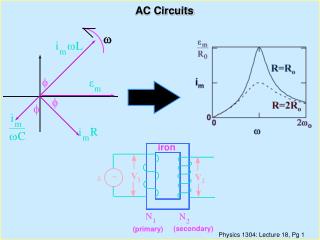
V(t) Vp wt p 2p fv -Vp An “AC” circuit is one in which the driving voltage and hence the current are sinusoidal in time. Alternating Current Circuits V = VP sin (wt - fv ) I = IP sin (wt - fI ) wis theangular frequency (angular speed) [radians per second]. Sometimes instead ofwwe use thefrequency f [cycles per second] Frequency f [cycles per second, or Hertz (Hz)]w= 2p f
V(t) Vp wt p 2p fv -Vp Phase Term V = VP sin (wt - fv )
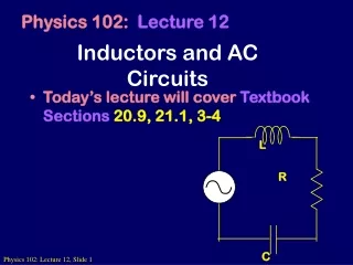
R E ~ Resistors in AC Circuits EMF (and also voltage across resistor): V = VP sin (wt) Hence by Ohm’s law, I=V/R: I = (VP /R) sin(wt) = IP sin(wt) (with IP=VP/R) V I V and I “In-phase” p wt 2p
C E ~ Start from: q = C V [V=Vpsin(wt)] Take derivative: dq/dt = C dV/dt So I = C dV/dt = C VPw cos (wt) I = C w VP sin (wt + p/2) Capacitors in AC Circuits This looks like IP=VP/R for a resistor (except for the phase change). So we call Xc = 1/(wC) the Capacitive Reactance V I wt p 2p The reactance is sort of like resistance in that IP=VP/Xc. Also, the current leads the voltage by 90o (phase difference). V and I “out of phase” by 90º. I leads V by 90º.
I Leads V???What the **(&@ does that mean?? 2 V f 1 I I = C w VP sin (wt + p/2) Current reaches it’s maximum at an earlier time than the voltage!
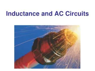
Inductors in AC Circuits V = VP sin (wt) Loop law: V +VL= 0 where VL = -L dI/dt Hence: dI/dt = (VP/L) sin(wt). Integrate: I = - (VP / Lw) cos (wt) or I = [VP /(wL)] sin (wt - p/2) ~ L V Again this looks like IP=VP/R for a resistor (except for the phase change). So we call XL = w L the Inductive Reactance I p wt 2p Here the current lags the voltage by 90o. V and I “out of phase” by 90º. I lags V by 90º.
Phasor Diagrams A phasor is an arrow whose length represents the amplitude of an AC voltage or current. The phasor rotates counterclockwise about the origin with the angular frequency of the AC quantity. Phasor diagrams are useful in solving complex AC circuits. The “y component” is the actual voltage or current. Resistor Vp Ip w t
Phasor Diagrams A phasor is an arrow whose length represents the amplitude of an AC voltage or current. The phasor rotates counterclockwise about the origin with the angular frequency of the AC quantity. Phasor diagrams are useful in solving complex AC circuits. The “y component” is the actual voltage or current. Resistor Capacitor Vp Ip Ip w t w t Vp
Phasor Diagrams A phasor is an arrow whose length represents the amplitude of an AC voltage or current. The phasor rotates counterclockwise about the origin with the angular frequency of the AC quantity. Phasor diagrams are useful in solving complex AC circuits. The “y component” is the actual voltage or current. Resistor Capacitor Inductor Vp Vp Ip Ip Ip w t w t w t Vp
i i + + + time i i LC Circuit i i + + +
Analyzing the L-C Circuit Total energy in the circuit: N o change in energy Differentiate :
Analyzing the L-C Circuit Total energy in the circuit: N o change in energy Differentiate :
Analyzing the L-C Circuit Total energy in the circuit: N o change in energy Differentiate :
Analyzing the L-C Circuit Total energy in the circuit: N o change in energy Differentiate : The charge sloshes back and forth with frequency w = (LC)-1/2
LC Oscillations C • Work out equation for LC circuit (loop rule) • Rewrite using i = dq/dt • (angular frequency) has dimensions of 1/t • Identical to equation of mass on spring L
LC Oscillations (2) • Solution is same as mass on spring oscillations • qmax is the maximum charge on capacitor • is an unknown phase (depends on initial conditions) • Calculate current: i = dq/dt • Thus both charge and current oscillate • Angular frequency , frequency f = /2 • Period: T = 2/
Energy Oscillations Equation of LC circuit • Total energy in circuit is conserved. Let’s see why (Multiply by i = dq/dt) Use UL + UC = const
Oscillation of Energies • Energies can be written as (using 2 = 1/LC) • Conservation of energy: • Energy oscillates between capacitor and inductor • Endless oscillation between electrical and magnetic energy • Just like oscillation between potential energy and kinetic energy for mass on spring
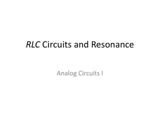
UNDRIVEN RLC Circuit • Work out equation using loop rule • Rewrite using i = dq/dt • Solution slightly more complicated than LC case • This is a damped oscillator (similar to mechanical case) • Amplitude of oscillations falls exponentially
RLC Circuit (Energy) Basic RLC equation Multiply by i = dq/dt Collect terms(similar to LC circuit) Total energy in circuit decreases at rate of i2R(dissipation of energy)
AC Circuits • Enormous impact of AC circuits • Power delivery • Radio transmitters and receivers • Tuners • Filters • Transformers • Basic components • R • L • C • Driving emf
AC Circuits and Forced Oscillations AC Circuits and Forced Oscillations • RLC + “driving” EMF with angular frequency d • General solution for current is sum of two terms “Steady state”:Constant amplitude “Transient”: Fallsexponentially & disappears Ignore
Steady State Solution • Assume steady state solution of form • Im is current amplitude • is phase by which current “lags” the driving EMF • Must determine Im and • Plug in solution: differentiate & integrate sin(t-) Substitute
Steady State Solution for AC Current (2) • Expand sin & cos expressions • Collect sindt & cosdt terms separately • These equations can be solved for Im and (next slide) High school trig! cosdt terms sindt terms
Steady State Solution for AC Current (3) • Solve for and Im in terms of • R, XL, XC and Z have dimensions of resistance • Let’s try to understand this solution using “phasors” Inductive “reactance” Capacitive “reactance” Total “impedance”
REMEMBER Phasor Diagrams? A phasor is an arrow whose length represents the amplitude of an AC voltage or current. The phasor rotates counterclockwise about the origin with the angular frequency of the AC quantity. Phasor diagrams are useful in solving complex AC circuits. Resistor Capacitor Inductor Vp Vp Ip Ip Ip w t w t w t Vp
Reactance - Phasor Diagrams Resistor Capacitor Inductor Vp Vp Ip Ip Ip w t w t w t Vp
R ~ L C “Impedance” of an AC Circuit The impedance, Z, of a circuit relates peak current to peak voltage: (Units: OHMS)
R ~ L C “Impedance” of an AC Circuit The impedance, Z, of a circuit relates peak current to peak voltage: (Units: OHMS) (This is the AC equivalent of Ohm’s law.)
R ~ L C Impedance of an RLC Circuit E As in DC circuits, we can use the loop method: E - VR - VC - VL = 0 I is same through all components.
R ~ L C Impedance of an RLC Circuit E As in DC circuits, we can use the loop method: E - VR - VC - VL = 0 I is same through all components. BUT: Voltages have different PHASES they add as PHASORS.
Ip Phasors for a Series RLC Circuit VRp VLp f VP (VCp- VLp) VCp
Ip Phasors for a Series RLC Circuit VRp VLp f VP (VCp- VLp) VCp By Pythagoras’ theorem: (VP )2 = [ (VRp )2 + (VCp - VLp)2 ]
Ip Phasors for a Series RLC Circuit VRp VLp f VP (VCp- VLp) VCp By Pythagoras’ theorem: (VP )2 = [ (VRp )2 + (VCp - VLp)2 ] = Ip2 R2 + (Ip XC - Ip XL)2
R ~ L C Impedance of an RLC Circuit Solve for the current:
R ~ L C Impedance of an RLC Circuit Solve for the current: Impedance:
IP W R = 1 0 R = 1 0 0 W 0 2 3 4 5 1 0 1 0 1 0 1 0 Impedance of an RLC Circuit The current’s magnitude depends on the driving frequency. When Z is a minimum, the current is a maximum. This happens at a resonance frequency: The circuit hits resonance when 1/wC-wL=0: w r=1/ When this happens the capacitor and inductor cancel each other and the circuit behaves purely resistively: IP=VP/R. L=1mH C=10mF The current dies away at both low and high frequencies. wr w
Ip VRp VLp f VP (VCp- VLp) VCp We can also find the phase: tan f = (VCp - VLp)/ VRp or; tan f = (XC-XL)/R. or tan f = (1/wC - wL) / R Phase in an RLC Circuit
Ip VRp VLp f VP (VCp- VLp) VCp We can also find the phase: tan f = (VCp - VLp)/ VRp or; tan f = (XC-XL)/R. or tan f = (1/wC - wL) / R Phase in an RLC Circuit More generally, in terms of impedance: cos f = R/Z At resonance the phase goes to zero (when the circuit becomes purely resistive, the current and voltage are in phase).
Power in an AC Circuit V f = 0 V(t) = VP sin (wt) I I(t) = IP sin (wt) p wt 2p (This is for a purely resistivecircuit.) P P(t) = IV = IP VP sin 2(wt) Note this oscillates twice as fast. p wt 2p
Power in an AC Circuit The power is P=IV. Since both I and V vary in time, so does the power: P is a function of time. Use, V = VP sin (wt) and I = IP sin (w t+f ) : P(t) = IpVpsin(wt) sin (w t+f ) This wiggles in time, usually very fast. What we usually care about is the time average of this: (T=1/f )
Power in an AC Circuit Now: Use: and: So