Download
1 / 33
330 likes | 337 Vues
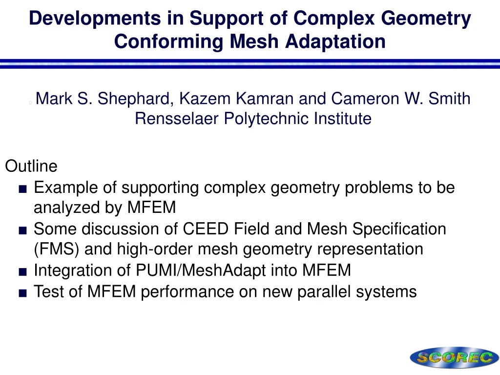
Developments in Support of Complex Geometry Conforming Mesh Adaptation. Mark S. Shephard, Kazem Kamran and Cameron W. Smith Rensselaer Polytechnic Institute Outline Example of supporting complex geometry problems to be analyzed by MFEM

E N D
Developments in Support of Complex Geometry Conforming Mesh Adaptation • Mark S. Shephard, Kazem Kamran and Cameron W. SmithRensselaer Polytechnic Institute Outline • Example of supporting complex geometry problems to be analyzed by MFEM • Some discussion of CEED Field and Mesh Specification (FMS) and high-order mesh geometry representation • Integration of PUMI/MeshAdapt into MFEM • Test of MFEM performance on new parallel systems
Integration of PUMI/MeshAdapt into MFEM • Status at last year’s review • In-memory of PUMI – load PUMI mesh and populate the MFEM data structures • Ability to curved straight sided elements to quadratic • Ability to inflate geometric approximation level • Efforts since last year: • Linking primary solutions variables from MFEM back to PUMI • Used simple projection based error indication based on primary variables to do adaptive demonstrations • Extension of MeshAdapt operators • Implemented a Navier Stokes element including adaptation based on projection of primary variables • Build is using Spack including possible Simmetrix link (available in the latest release of MFEM) 2
Supporting Analysis Geometry • Analysis geometry is what is meshed: • Derived/constructed from high level information • Differences between analysis geometry and the original higher level domain definition can include: • Clean-up to account for lack of model fidelity that limits meshing robustness • To ignore detail not required in the analysis • To alter the model based on modeling assumptions (e.g., dimensional reductions for things like beams and plates) • Addition of physics geometry that will be reflected in the modeling methods and/or mesh • Analysis driven geometry changes 3
Support of Analysis Geometry Construction Uses Simmetrix software components • Maintains combinations of non-manifold and assembly boundary representations • Accepts and combines geometry from: • CAD – with or without direct modeler links • Image data to boundary representation • Support faceted models • Supports common modeling operations needed for analysis mode construction • Supports model defeaturing • Supports meshing and analysis operations through APIs • Supports parallel geometry
Geometry and Meshing for RF Simulations • Accurate RF simulations require • Detailed antenna CAD geometry • Extracted physics curves from EFIT • Faceted surfaces from coupled meshes • Analysis geometry combining CAD, physics geometry and faceted interfaces • Well controlled 3D meshes for accurate FE calculations in MFEM • Integration with up-stream and down- stream simulation codes Developments underway • Tools for combining and interacting with geometry from multiple sources • Integration with curved mesh generation • Parallel curved mesh adaptation integrated into MFEM • Integration into the RF simulation workflow Simplified antenna array and plasma surface merged into reactor geometry and meshed
RF Analysis Geometry • De-featuring Antenna CAD: • Models have unneeded details • SimModeler provides toolsto “de-feature” CAD models • Bolts, mounts & capping holesremoved, closed non-manifold models constructed Combining Geometry: • Import components: • De-featured CAD assemblies • EFIT curves for SOL (psi = 1.05) • TORIC outer surface mesh • Create rotated surfaces from cross section curves • Assemble components into analysis geometry 6
Generate Curved Mesh for RF Simulations • Mesh controls set on Analysis Geometry • Mesh generation – linear oror quadratic curved meshed • Order inflation up to 6th order Linear mesh 8M elements Quadratic mesh 2.5M elements • 8M elements mesh with refined SOL 7
CEED Field and Mesh Specification • Comments on key features of importance for integration with other tools • The direct use of the hierarchy of mesh topology – supports linkage to high-level geometry and problem specification, and the effective construction of a complete representation needed for conforming mesh adaptation • The explicit inclusion of the mesh entities fro 0D to 3D – supports associating field information with mesh entities • Treating mesh geometry as a field like any other • Mesh geometry • Most coming from FE world (p-version people) favor interpolating geometry – can be noisy and require more work • CAD and isogeometry people favor approximating geometry • NURBS • Bezier geometry 8
Mesh Topology Representations • Brief discussion of mesh topology • Complete – get any adjacency in O(1) time • Full – Explicitly represents all mesh entities • PUMI currently uses one level (this is not exposed to users) • Recommend full with downward pointers for CEED file Region Region Region Face Face Face ClassicFEincompletenot full Region Edge Edge Edge Vertex Min. Complete completenot full(was implemented) Vertex Vertex Vertex A view of FMS One levelcompletefull Circularcompletefull PUMI
Mesh Topology Representation • Why a full topology with downward pointers (only) • Loading mesh requires a mesh traversal – We can construct any other need adjacencies at that time • For a given “element topology” all downward adjacencies are to a fixed number of entities –CEED has limited number of elementtopologies – can take advantage of this • Want a full topology since there are fields associated with all mesh entities(not just equal order classified entities –can explain if interested in knowing) • Although there will be some mapping tospecific FEM code structures that definesregions, faces and edges as vertex lists –it is easy to construct from a fulldownward – reverse not so nice Region Region Face Face Edge Edge Vertex Vertex FMSincompletefull Circularcompletefull 10
FMS-PUMI data exchange: Topology • As PUMI data structure supports one-level downward adjacencies the task of generating FMS mesh object, FmsMesh, is straight forward: • Use PUMI API’s to loop over each entity type, get the bounding vertices IDs and then call FMS API’s to construct the corresponding entity. Writing all triangle faces
FMS-PUMI data exchange: Shape • The mesh shape is defined using the coordinate field • FMS has a field descriptor that defines field properties such as continuity, basis type and order • The order of data storage for a field is to first add data associated to vertices and then data for the nodes classified on Edges > Faces > Volume • In our quadratic mesh example we have only coordinates field data associated with vertices and edges Writing FMS coordinate field
Mesh Geometry • Lagrange interpolation is a poor choice • Now common knowledge due to interest in isogeometric • There is still a strong attraction to interpolating methods • Used by many high-order codes – must use carefully selected interpolating points to have reasonable control • Bezier approximation polynomials more effective • Use as basis functions now common (due to isogeometric) • More important to used for geometry than basis • Their advantages are of substantial value for curved mesh generation and mesh adaptation processes • Easier control of geometric approximation • More effective for developing algorithms used to control element validity and quality • Prefer to stay away for rational forms • Increases meshing algorithm complexity and cost • No benefit since general meshes approximate geometry 13
Bezier Geometry in Curved Meshing • Advantageous properties of Bezier polynomials • Can be as high a degree as desired • Better geometric approximation properties • Convex hull provides support efficient numerical algorithms • Support efficient intersection checks • Derivatives and products of Beziers are also Beziers • Efficient algorithms for degree elevation and subdivision • Mesh region validity determination • Traditional validation methods test the Jacobian at integration points • Validation for Bezier Regions is provided – region is valid if the minimum control point of the Jacobian determinant function is > 0 14
Correcting an Invalid Entity by Shape Modification • Determine key mesh entities to prevent shape movement • Identify each • Find the dominating pair of partial vectors causing each • Count the appearance number of each partial vectors • Key entities - for the partial vector(s) which has the biggest appearance number, find the mesh entities which control points form the vector(s) • Vector appears most frequently in the counting • Mesh edge is the key entity 15
Curved Operations - Re-curving • The box product terms that compose the Jacobian determinant function can be used to determine how a region should be corrected Invalid Tet caused by moving P1 - note that a • (b x c) < 0 • Jacobian Control point, Jl for a tet region of degree d is: 16
Curved Operations – Edge Swap • Determine shape constraint curved cavity • Define “plane” to be re-triangulated • For each possible topological triangulation of the curved cavity, use blending method to construct new entity shape • Check whether the new mesh configuration with new shape is valid • Ensure all the new regions have positive determinant of Jacobian 17
Curved Operations – Edge Collapse • Apply blending method to compute the control points for the new entities • New entities are constructed in a order from the nearest to the furthest vertex neighboring to the remaining vertex • Advantage – constraint the new entity shape inside a set of curved quadrilateral polygons without interfering neighbors • Example Collapse edge 18
quadratic cubic quartic 0.9897 0.5006 0.4648 0.0702 0.0355 0.0329 collapse 2 1 1 linear 1.7028 0.1208 Swap 3 1 1 Split 17 17 17 Recurving 29 15 14 Refinement 10 3 2 Example High Order Curving linear mesh geometric model quadratic mesh cubic mesh quartic mesh 19
Curved Mesh Adaptation • Anisotropic curved mesh adaptation • Employs links from mesh to geometry • Employs Bezier mesh geometry for the mesh faces 20 20
Mesh Modification to Eliminate Flat Elements • Four types of flat elements • Type 1 – edges V0-V2& V1-V3 nearly intersect • Type 2 – vertex V3 is close to face V0-V1-V2 • Type 3 – vertex V3 is close to edge V0-V1 • Type 4 – edge V0-V3 is short • Eliminating the flat elements • Type 4 – easy to detect, edge collapse is the desired operation • Types 1-3 – harder to detect – use a projection • Types 1-3 – require compound operators to eliminate 21
Mesh Modification to Eliminate Flat Elements • Type 1: Doubleedge split plusedge collapse Type 2: Facesplit plus edgecollapse Type 3 Edgesplit plus edgecollapse 22
MeshAdapt example • Adding pumimeshAdapt in MFEM • After solving on the initial mesh solution fields are passed from MFEM to PUMI mesh. • Using PUMI APIs a size field is computed from the solution field • MeshAdapt, for linear, or CurveAdapt, for second order, is performed given the size field • New mesh is loaded in MFEM • Fields are transferred back from PUMI to updated MFEM • Boundary and domain integrators are updated and BCs are applied using classification 23
MeshAdapt example • Functionalities developed – Primary field values only at this time: • Solution transfer from MFEM to PUMI: Developed for linear and high order elements. Build a template for all dof holders on vertices, faces, edges and transfer them to them PUMi field • FieldMFEMtoPUMI: for scalar field transfer, takes the MFEM mesh and solution GridFunction and return a PUMI field • VectorFieldMFEMtoPUMI: for vector field transfer • Solution transfer from PUMI to MFEM: Developed for linear and quadratic elements. Similar to the coordinate filed transfer already done during mesh loading. • FieldMFEMtoPUMI: for scalar field transfer, takes PUMI mesh and field and return the MFEM’s Gridfunction. • VectorFieldMFEMtoPUMI: for vector field transfer 24
MeshAdapt example • This example solves a linear elasticity problem: • Lame constants are: lambda = mu = 1 • Left face shown in red is fixed • Opposite face is pulled by f = 0.01 • Initial mesh of 5k is used Model with fixed boundary marked in red Initial linear mesh 25
MeshAdapt - Linear Final linear mesh Initial linear mesh 26
MeshAdapt - Quadratic Final quadratic mesh Initial quadratic mesh 27
Navier-Stokes implementation • Stabilized multiscale NS; find {u,p} such that for each {v,q} • Equal order velocity/pressure finite element • Start with the stationary stabilized Stokes • And the components are 28
Navier-Stokes implementation • Given the block structure of the problem, we use BlockVectorto define x={u,p} and BlockMatrix to define the system matrix. • The BilinearForm is used for matrices M and Q while the MixedBilinearForm is used for the matrix B. • New domain integrators are added as needed: • StabLaplacianIntegratorfor pressure stab. term Q • VectorDivIntegratorfor divergence stab. term • StabGradDomainLFIntegrator for force term • As the same finite element, H1_FECollection, is used for both velocity and pressure, only the dimension is different, an easier approach would be to define a single finite element space of dimension “dim+1” for {u,p}. 29
N.S. Driven Cavity • The implementation is tested for the driven cavity (Re=100) • Uniform mesh is considered as the starting mesh • Once the solution is obtained MixedMFEMtoPUMIAPI is used to transfer the {p,u} solution field to pumi mesh. • A ZZ error estimation is performed using velocity gradient to get the adaptation size field. Initial Solution Initial mesh 30
N.S. Driven Cavity Mesh after meshAdapt for linear and quadratic solution Quadratic Linear 31
N.S. Driven Cavity Mesh after meshAdapt for linear and quadratic solution Quadratic Linear 32
Ongoing/Planned Efforts • Continued advancement of curved mesh adaptation functions – an emphasis on higher order than quadratic • Error indicators for high-order elements (should closely coordinate with MFEM code developers) • Consideration of element shape degradation for time dependent Lagrangian flow applications • Demonstration –Laghosminiapp • Consideration of the use of EnGPar for dynamic partition improvement and dynamic load balancing during mesh adaptation. • Clean integration into PyFEM for PetraM RF applications • Additional efforts on the CEED Filed and Mesh Specification