Download
1 / 27
320 likes | 575 Vues
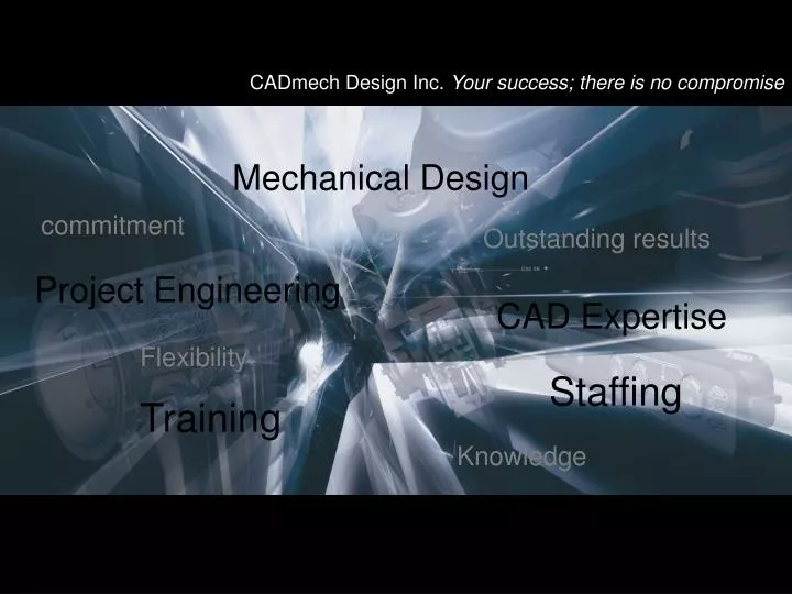
Mechanical Design. commitment. Outstanding results. Project Engineering. CAD Expertise. Flexibility. Staffing. Training. Knowledge. Application of Wave Technology in Die Design Process. Seamless integration of part design information into tooling design process. We’ll talk about

E N D
Mechanical Design commitment Outstanding results Project Engineering CAD Expertise Flexibility Staffing Training Knowledge
Application of Wave Technology in Die Design Process Seamless integration of part design information into tooling design process
We’ll talk about Application of WAVE functionality: create and control upstream flow of design information “do things right from the beginning”
Our case study – ‘COOL RIM’ • Techniques for die-cast tooling design process: applied to any popular molding technology • Integrates cool rimpart design into die components • Demonstrates propagation of part geometry changes to die assembly
‘COOL RIM’ – WAVE Facts WAVE – UG/NX technology of linking inter-part geometry creation of inter-part dependencies Works on part topology level Wave Geometry Linker Requires assembly environment does not require WAVE control license
‘COOL RIM’ – Flow of Information Vertical WAVE Linking (in series) Machined Part Casting Part Cavity Trim Part
‘COOL RIM’ – Machined Part Step 1: “as machined” model Development of end product (as machined) Integration of casting design intent For effective design‘clean geometry’ is essential Proper file organization Modeling discipline and diligence
‘COOL RIM’ – Casting Part Step 2: ”As cast” model Vertical wave link in time stamp Additional casting features: shut-offs added to casting model
‘COOL RIM’ – Cavity Trim Part Step 3: Cavity Trim Part Vertical wave link to casting model Apply shrinkage factor for cast material (scale feature) Extracted cavity regions – along parting line divisions Tooling seal-off faces developed and attached to appropriate cavity regions to form unique cavity trimming tools
‘COOL RIM’ – Flow of Information Horizontal WAVE Linking (in parallel) Die Top Level Assembly Die Component Cavity Trim Part Cover Insert Ejector Insert Slide#1 Slide#2
‘COOL RIM’ – Die Component Startup die component model: extruded block controlled by sketch Add to top level die assembly: waved into each cavity component horizontal wave link Overall die dimensions: controlled from single file die component
‘COOL RIM’ – Cover Insert Step#1 WAVE linked bodies Step#2 Cavity trim operation Step#3 Final component
‘COOL RIM’ – Ejector Insert Step#1 WAVE linked bodies Step#2 Cavity trim operation Step#3 Final component
‘COOL RIM’ – Slide#1 Step#1 WAVE linked bodies Step#2 Cavity trim operation Step#3 Final component
‘COOL RIM’ – Slide#2 Step#1 WAVE linked bodies Step#2 Cavity trim operation Step#3 Final component
‘COOL RIM’ – Die Top Level Assembly Final step in design integration process From part model level to tool assembly level Part design changes will propagate to tooling components through top level die assembly model
‘COOL RIM’ – How does it work? UPDATED COVER INSERT` FROM TO
What is important for successful design? File organization: keep it simple and straightforward Proper and efficient use of modeling techniques Efficient WAVE management
GOOD Design Practices Layer structure / category naming convention Modeling tree structure – feature sequence/grouping feature naming Expression/formula definition Defined geometry reference sets File Organization:
GOOD Design Practices Fixed datums and primitives: as startup features only Don’t be afraid of using sketches: avoid using non-parametric “flying” wireframe Don’t multiply features: especially datums Don’t patch model by adding features over existing ones Don’t build deep model dependencies Always check validity of model geometry Modeling Techniques:
GOOD Design Practices Upfront planning investment into model and file organization and diligence in keeping model files “clean & lean” will bring multiple benefits to seamless flow of design information
WAVE Management Efficient WAVE management without WAVE Control License Vertical (serial) WAVE linking Horizontal (parallel) WAVE linking Managing WAVE links - breaking, reattaching, up dating links
WAVE Geometry Linker – What are the benefits? Full parametric integration of part design data into tooling design process Flexible management of linking process “Geometry safe” method Reasonable file sizes No additional license required Helps even with “challenging part geometry”
Problem Geometry – How to deal with it? Topology problems must be fixed – clean topology is a MUST for math data integrity Well defined and simplified parting lines With clean part geometry, even non-parametric data integration can proceed WAVE management is critical to preserve tooling data integrity – breaking and re-establishing WAVE links, delayed updates
Mechanical Design commitment Outstanding results Project Engineering CAD Expertise Flexibility Staffing Training Knowledge