Download
1 / 62
920 likes | 1.45k Vues
Transient Liquid Phase Bonding as a Potential Substitute for Soldering with High-Lead Alloys A.A. Kodentsov Laboratory of Materials and Interface Chemistry, Eindhoven University of Technology, The Netherlands.

E N D
Transient Liquid Phase Bonding as a Potential Substitute for Soldering with High-Lead Alloys A.A. Kodentsov Laboratory of Materials and Interface Chemistry, Eindhoven University of Technology, The Netherlands
There is still no obvious (cost-effective) replacement for high-lead, high melting ( 260 - 320 C) solder alloys • It is not possible to adjust (to increase above 260 C) liquidus temperature of any existing Sn-based solder alloys by simple alloying with environmentally friendly and inexpensive elements • Therefore, in the quest for (cost-effective) replacements of the high-lead solders, attention has to be turned towards different base metals as well as the exploration of alternative joining techniques !
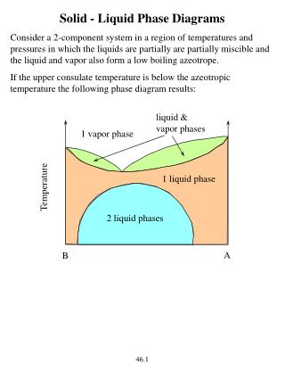
Liquidus projection of the Zn-Al-Mg system Ternary eutectic at ~ 343 C
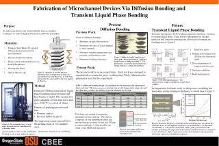
Transient Liquid Phase (TLP) Bonding solid solid interlayer(s) solid • The interlayers are designed to form a thin or partial layer of a transient liquid phase (TLP) to facilitate bonding via a brazing-like process in which the liquid disappears isothermally • In contrast to conventional brazing, the liquid disappears, and a higher melting point phase is formed at the bonding temperature
Transient Liquid Phase (TLP) Bonding solid solid solid solid product T= const liquid solid solid solid T= const Diffusion, Reaction solid Any system wherein a liquid phase disappears by diffusion, reaction (amalgamation), volatilization, or other processes is a candidate for TLP bonding !
The effect of Ni additives in the Cu-substrate on the interfacial reaction with Sn
Diffusion zone morphology developed between Cu and Sn after reaction at 215 C in vacuum for 225 hrs In the -Cu6Sn5:
Reaction zone developed between Sn and Cu 1at.% Ni alloy after annealing at 215 C for 400 hrs pores !!!
Reaction zone developed between Sn and Cu 5at.% Ni alloy after annealing at 215 C for 400 hrs No pores !!! No -Cu3Sn was detected!
Isothermal sections through the Sn-Cu-Ni phase diagram P. Oberndorff, 2001 C.H. Lin, 2001 235 C 240 C
Part of the Cu-Sn phase diagram in the vicinity of the / transition Simple Superlattice Long-Period Superlattice
Cu5Ni Sn Cu5Ni (Cu,Ni)6Sn5 Sn Sn (Cu,Ni)6Sn5 Cu5Ni Cu5Ni (Cu,Ni)6Sn5 250 C Kirkendall plane (s) Cu5Ni Cu5Ni Cu5Ni Cu5Ni 250 C Ag Cu5Ni
Binary phase diagram Ni-Bi 250 C
Ni Bi Ni NiBi3 Bi Bi NiBi3 Ni Ni NiBi3 280 C Kirkendall plane (s) Cu5Ni Ni Ni Ni 280 C Ag Cu5Ni Ni
Concluding Remarks • It is not possible to adjust (to increase above 260 C) liquidus temperature of any existing Sn-based solder alloys by simple alloying with environmentally friendly and inexpensive elements • Therefore, in the quest for (cost-effective) substitutes for high-lead solders, attention has to be turned towards different base metals as well as the exploration of alternative joining techniques ! • Through the judicious selection of Sn- or Bi-based interlayer between under bump metallization and substrate pad, (cost-effective) Transient Liquid Phase (TLP) Bonding can be achieved at ~ 250-280 C, and the resulting joints are capable of service at elevated temperatures ! • The TLP Bonding should be taken into further consideration as substitute for the high-lead soldering !
Diffusion zone morphology developed between Cu and Sn after reaction at 215 C in vacuum for 225 hrs
Parabolic growth of the Cu-Sn intermetallic layers in the binary diffusion couples at 215 C 1.58 x 10⁻¹⁶ m2/s 7.55 x 10⁻¹⁷ m2/s
Diffusion zone morphology developed between Cu and Sn after reaction at 215 C in vacuum for 225 hrs
Determination of the ratio of intrinsic diffusivities of species in line-compounds
Diffusion zone morphology developed between Cu and Sn after reaction at 215 C in vacuum for 225 hrs In the -Cu6Sn5:
The Cu3Ti – type lattice (oP 8), the basic structure of the long-period superstucture of the -Cu3Sn Ti Cu The hexagonal analog of L12-structure of Cu3Au ! Cu Ti View down [010]
The basic structure (oP 8 ) The hexagonal analog of the Cu3Au! • Sn has 12 Cu NN • Cu has 4 Sn and 8 Cu NN • There are no Sn - SnNN c0 b0 a0 • In the Long-Period Superstructure of -Cu3Sn (oC80 ) antiphase shifts occur at every fifth period along the b0-axis (a=2a0; b=10b0; c=c0) Projection onto (001) plane
“The ordered Cu3Au rule” L12 - type structure (A3B) • The nearest neighbour (NN) arrangement of A-atoms • The nearest neighbour arrangement of B-atoms
Reaction zone developed between Sn and Cu after annealing at 215 C for 400 hrs markers!!!
Reaction zone developed between Sn and Cu after annealing at 215 C for 400 hrs
Reaction zone developed between Sn and Cu 1at.% Ni alloy after annealing at 215 C for 400 hrs pores !!!
Reaction zone developed between Sn and Cu 5at.% Ni alloy after annealing at 215 C for 400 hrs No -Cu3Sn was detected!
Isothermal sections through the Sn-Cu-Ni phase diagram P. Oberndorff, 2001 C.H. Lin, 2001 235 C 240 C
Reaction zone developed between Sn and Cu 1at.% Ni alloy after annealing at 215 C for 400 hrs
Isothermal section through the Sn-Cu-Ni phase diagram at 235 C. (P. Oberndorff, Ph. D. Thesis, Eindhoven University of Technology, The Netherlands, 2001) Cu 1at.% Ni
Isothermal section through the Sn-Cu-Ni phase diagram at 240 C. (C.H. Lin, Master Thesis, National Tsing-Hua University, Republic of China, 2001) Cu 1at.% Ni
Reaction zone developed between Sn and Cu 5at.% Ni alloy after annealing at 215 C for 400 hrs
Isothermal section through the Sn-Cu-Ni phase diagram at 235 C. (P. Oberndorff, Ph. D. Thesis, Eindhoven University of Technology, The Netherlands, 2001) Cu 5at.% Ni
Isothermal section through the Sn-Cu-Ni phase diagram at 240 C. (C.H. Lin, Master Thesis, National Tsing-Hua University, Republic of China, 2001) Cu 5at.% Ni
Diffusion zone morphology developed between Cu and Sn after reaction at 215 C in vacuum for 225 hrs In the -Cu6Sn5:
The NiAs- type lattice the basic structure of the -Cu6Sn5 hP 4 tetrahedral hole octahedral hole trigonal hole
Pictorial view of the NiAs (hP4 ) structure • Ni has 6 As NN A C • As is surrounded by 6 Ni A B A C • The As octahedra share faces normal to the c-axis A B A • The Ni-atoms are direct neighbours along [001] direction
The composition “Cu6Sn5” is achieved by adding additional Cu-atoms inone tenth of the tetrahedral interstices in the hexagonal Sn-sublattice Cu Sn
1. Ordering of the excess Cu-atoms in the tetrahedral interstices results in the /-Long-Period Superlattice Cu Sn
2. The excess Cu-atoms occupy the tetrahedral interstices at random Cu c a1 a2 c/2 Sn Type A Type B • An arrangement of the unit cells along the three principle axes in the sequence ABABAABABA … results in the supercell of the /-phase