Download
1 / 11
110 likes | 228 Vues
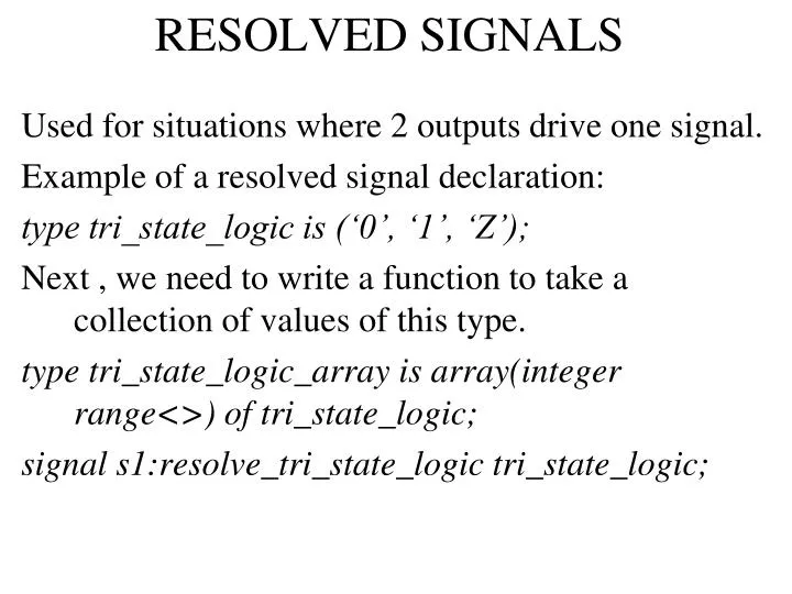
RESOLVED SIGNALS. Used for situations where 2 outputs drive one signal. Example of a resolved signal declaration: type tri_state_logic is (‘0’, ‘1’, ‘Z’); Next , we need to write a function to take a collection of values of this type.

E N D
RESOLVED SIGNALS Used for situations where 2 outputs drive one signal. Example of a resolved signal declaration: type tri_state_logic is (‘0’, ‘1’, ‘Z’); Next , we need to write a function to take a collection of values of this type. type tri_state_logic_array is array(integer range<>) of tri_state_logic; signal s1:resolve_tri_state_logic tri_state_logic;
RESOLVED SIGNALS Example1: A resolution function for resolving multiple values from tristate drivers. function resolve_tri_state_logic(values: in tri_state_logic_array) return tri_state_logic_is variable result:= tri_state_logic:=‘Z’; begin for index in values’range loop if values(index) /= Z then result := values(index); end if; end loop; return result; end function resolve_tri_state_logic;
RESOLVED SIGNALS The following example shows a package interface and the corresponding package body for the 4 state multivalued logic type. The constant resolution_table is a lookup table used to determine the value resulting from two source contributions to a signal of the resolved logic type. package mvl4 is type mvl4_ulogic is (‘X’,’0’,’1’,’Z’); type mvl4_ulogic_vector is array(natural range <>) of mvl4_ulogic; function resolve_mvl4(contribution: mvl4_ulogic_vector) return mvl4_ulogic; subtype mvl4_logic is resolve_mvl4 mvl4_ulogic; end package mvl4;
RESOLVED SIGNALS package body mvl4 is type table is array(mvl4_ulogic, mvl4_ulogic) of mvl4_ulogic; constant resolution_table : table := ((‘X’, ‘X’,’X’,’X’), (‘X’,’0’,’X’,’0’), (‘X’,’X’,’1’,’1’), (‘X’,’0’,’1’,’Z’)); function resolve_mlv4(contribution : mlv4_ulogic_vector) return mvl4_ulogic is variable result : mvl4_ulogic := ‘z’; begin for index in contribution’range loop result := resolution_table(result, contribution(index)); end loop; return result; end function resolve_mvl4; end package body mvl4;
RESOLVED SIGNALS Composite resolved subtypes: The following example shows a package interface and body that define a resolved array subtype. Each element of an array value of this subtype can be ‘X’,’0’,’1’ or ‘Z’. The resolved type uword is a 32 element value of these values. package words is type x01z is (‘X’,’0’,’1’,’Z’); type uword is array (0 to 31) of x01z; type uword_vector is array(natural range <>) of uword; function resolve_word(contribution : uword_vector) return uword; subtype word is resolve_word uword; end package words;
RESOLVED SIGNALS package body words is type table is array(x01z, x01z) of x01z; constant resolution_table :table := ((‘X’, ‘X’,’X’,’X’), (‘X’,’0’,’X’,’0’), (‘X’,’X’,’1’,’1’), (‘X’,’0’,’1’,’Z’)); function resolve_word (contribution : uword_vector) return uword is begin for index in contribution’range loop for element in uword’range loop result(element) := resolution_table(result(element), contribution(index)(element)); end loop; end loop; return result; end function resolve_word; end package words;
RESOLVED SIGNALS The next example shows an entity declaration for a bus module that has a port of the unresolved type std_ulogic for connection to such a synchronization control signal. The architecture body for a system comprising several such modules is also outlined. library ieee; entity bus_module is port(synch : inout std_ulogic ...); end entity bus_module; architecture top_level of bus_based_system is signal synch_control : std_logic; begin synch_control_pull_up : synch_control <= ‘H’; bus_module_1 : entity work.bus_module(behavioral) port map(synch => synch_control ....); bus_module_2 : entity work.bus_module(behavioral) port map(synch => synch_control ....); ....... end architecture top_level;
RESOLVED SIGNALS The next example is an outline of a behavioral architecture body for a bus module, showing use of the synchronization control port: architecture behavioral of bus_module is begin behavior : process is ... begin synch <= ‘0’ after Tdelay_synch; .... synch <= ‘Z’ after Tdelay_synch; wait until synch = ‘H’; .... end process behavior; end architecture behavioral;
RESOLVED SIGNALS This figure shows the hierarchical organization of a single board computer system consisting of a video display, an input/output controller, a CPU/memory section and a bus expansion block. The CPU consists of memory block and a cache block. Both these act as sources for the data port, so it must be a resolved port. The cache has 2 sections, both act as its sources. Hence, this is also a resolved port.
RESOLVED SIGNALS Consider a case of one of the cache sections updating its data port. The new driving value is resolved with the current driving value form the other cache section to determine the driving value of the CPU/cache block data port. This result is then resolved with the current driving value of the memory block to determine the driving value of the CPU/memory section. Next, this driving value is resolved with the current driving values of the other top level sections to determine the effective value of the data bus signal. The final step is to propagate this signal value back down the hierarchy for use as the effective value of each of the data ports. Thus, a module that reads the value of its data port will see the final resolved value of the data bus signal.