Download
1 / 11
110 likes | 220 Vues
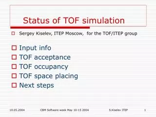
Status of the TOF Low Voltage System. Salvatore de Pasquale INFN Bologna. TOF-LVS Distribution Overview. Detector Layout: 18 barrel sectors, 5 modules per sector 1 central module containing 15 strips 2 intermediate modules containing each one 20 strips

E N D
Status of the TOF Low Voltage System Salvatore de Pasquale INFN Bologna Salvatore De Pasquale INFN Bologna
TOF-LVS Distribution Overview Detector Layout:18 barrel sectors, 5 modules per sector 1 central module containing 15 strips 2 intermediate modules containing each one 20 strips 2 external module containing each one 19 strips Strip layout:1strip = 96 read-out pads (channels) 93 Strips per sector; Total # of Strips = 1674 FEC:32-channels card hosting amplifiers, comparators and the high resolution TDCs Each strip is read out by 3 FECs 45, 60 or 57 FECs per module Total # of FECs = 5022 Number of channels:1440, 1920 or 1824 channels per module 8928 channels per sector Total # of channels = 160704 Salvatore De Pasquale INFN Bologna
TOF-LVS Distribution Overview Read-Out Controller(ROC):Each ROC can drive a maximum of 16 FEC Size of a ROC card = roughly as 1.5 FEC 3 ROCs for the central module 4 ROCs both for intermediate and external modules Total # of ROC = 342 Multipl. Data Transfer(MDT):1 MDT per module Size of MDT card = roughly as 1.5 FEC Total # of MDT = 90 Summary of the Electronics to be installed in a Module Central Module:45 FECs, 3 ROCs, 1 MDT Intermediate Module:60 FECs, 4 ROCs, 1 MDT External Module:57 FECs, 4 ROCs, 1 MDT Salvatore De Pasquale INFN Bologna
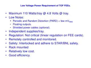
TOF-LVS Distribution Overview (Cont’d) Power consumption per channel:FEA= 130mW (ASIC) or 300mW (No ASIC) TDC= 110mW Logic (FPGA)= 50mW Analog (DAC)= 60mW Contingency= 50mW Total(ASIC): Pnom = 400mW, Pmax = 500mW Total(non ASIC): Pnom = 570mW, Pmax = 712mW Digital and Analog circuitries will be totally independent Power consumption per module:Power=1.37 kW(~0.71 digital and ~0.66 analog) Current for 6V (analog line)= 110 A Current for 6V (digital line)= 118 A Power consumption per sector:Power=6.37 kW(~3.3 digital and ~3.1 analog) Current for 6V (analog line)= 525 A Current for 6V (digital line)= 550 A Total Power consumption:ASIC solution: Pnom= 64.3kW, Pmax= 80.3kW Non ASIC solution: Pnom= 91.6kW, Pmax= 114.4kW Major power consumer in ALICE Salvatore De Pasquale INFN Bologna
TOF-LVS Segmentation In the more power consuming scenario and considering a conventional distribution: LV power supply which provide the appropriate voltage to the cards (e.g. +5V; –5V) in the distribution arm to a sector have to circulate currents of about 1100 A and a total current of about 20000 Ato the whole detector. We take, as an example, the WIENER Modular Power Supply system series PL 500 F arranged in 3U size modules. We consider the MEH type power module (6V, 90A switching power supply). 6x3U units are used to feed the analog circuitry of a complete sector. 6x3U units are used to feed the digital circuitry of a complete sector. A total number of 216WIENER PL500F 3U modules are needed to power the whole TOF They can be arranged into 44 3U crates (5x3U units per crate) hosted in 8 racks (low voltage racks) located on both sides of the detector. (This segmentation is just an indication and is not yet optimized) Salvatore De Pasquale INFN Bologna
TOF-LVS Segmentation Space Frame Bar Cooling shield Magnet door TOF Module 6V 90A 10 mm 44 Low Voltage 3U crates 10 mm 2x18 6V 90A DV<1V 216 bus-bars 100 mm2 each 8 Low Voltage racks Salvatore De Pasquale INFN Bologna
TOF-LVS Segmentation Assuming a voltage drop < 1V over a distance of 40 m (the average distance between the racks area and the space frame) we need cables (bus-bars, cooled inside the L3 magnet) with a square section of about 100 mm2to connect each LV power supply unit with the TOF detector. 216 bus-bars of 100 mm2 are needed for the whole detector. Each line will be connected, through a flexible cable, to patch panels, located on the space frame bar. The patch panel will then ensure the distribution, both for the analog and digital circuits, to the single TOF modules front-end electronics Salvatore De Pasquale INFN Bologna
TOF-LVS Distribution (another approach) To reduce the huge amount of current on the distribution lines, we can adopt a different approach: a Low Voltage power distribution with the use of high voltage (48 Volts) power supplies associated with DC/DC converters inside the detector The main concern is: are there available reliable DC/DC converters which can work in a high radiation and high magnetic field environment? ************** We started, at the beginning of this year, a collaboration with CAEN to develop DC/DC converter capable to work up to 5000 Gauss and sufficiently rad-hard for the purpose of the TOF. On June 14th , a first CAEN prototype of DC/DC converter (150W) has been successfully tested at CERN in a magnetic field of 1850 Gauss (thanks to the Electronic Pool). Salvatore De Pasquale INFN Bologna
TOF-LVS Distribution (another approach) Considering a power supply of 48V and 150 A: only one power supply is needed to power an entire sector (a total of 18 48V PS) just one 40m bus-bar 12x12 mm2 per sector is needed to connect the 48V PS to the space frame near the TOF modules. The bus-bars are then connected, through flexible cables, to a patch panel that distribute the power to 5 or 6 DC/DC converter (240W to 280W) located inside each TOF module. A total number of 90 or 108 DC/DC converter is needed to power the whole TOF The DC/DC converter will be equipped also with filters and control units able to read-out various parameters and switch on and off groups of front-end cards. Planning: Test DC/DC converter up to 5000 Gauss and check for reliability and robustness. Salvatore De Pasquale INFN Bologna
VFE module VFE module VFE module VFE module slave card 5 channel slave card 5 channel slave card 5 channel slave card 5 channel slave card 5 channel slave card 5 channel slave card 5 channel slave card 5 channel Distribution scheme to a TOF Sector (another approach) Cables running to each module Flexible cable ~40m Bus Bars LV PS 48V in the racks area Patch panel on the S.F. bar Screw Joint cooled cooled cooled Feed Through TOF Module DC/DC converter with filters and controls (placed inside the module) 15, 20 or 19 strips in each module Strips FEC Front End Card 32 channels FEC Front End Card 32 channels FEC Front End Card 32 channels FEC Front End Card 32 channels FEC Front End Card 32 channels Salvatore De Pasquale INFN Bologna
LVS Distribution (another approach) Space Frame Bar HV Patch Panel LV Patch Panel Signals and Services Patch Panel 48V line TOF Module Bus Bar Salvatore De Pasquale INFN Bologna