Download
1 / 13
130 likes | 285 Vues
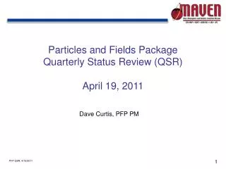
Presentation to CCIC: ITER-like JET ICRH Antenna Status of Arc Detection. Mark Nightingale (on behalf of Frederic Durodie, Ernesto Lerche, Trevor Blackman, Mark Vrancken & Philippe Jacquet). Introduction. 2. C. 1. C. Strap 2. Strap 1.

E N D
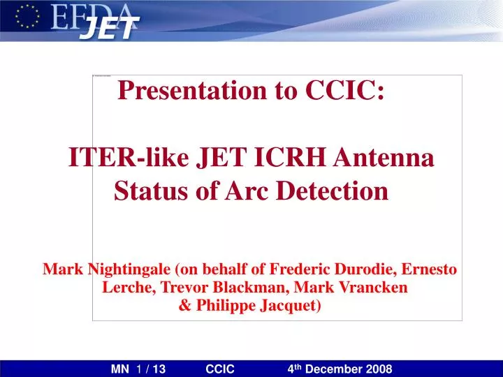
Presentation to CCIC:ITER-like JET ICRH AntennaStatus of Arc Detection Mark Nightingale (on behalf of Frederic Durodie, Ernesto Lerche, Trevor Blackman, Mark Vrancken & Philippe Jacquet)
Introduction 2 C 1 C Strap 2 Strap 1 • Key objective of the JET ITER-like antenna (ILA) is to couple power throughout large ELMs (ELM tolerance) by running the antenna in conjugate-T mode with a low (3W) impedance at the T-point. • Using a 3W conjugate-T introduces a risk: arcing close to the T-point does not result in high swings in VSWR on the incoming transmission lines. • Two new arc detection schemes have been fitted to the ILA. The Sub-harmonic Arc Detection (SHAD) system is not yet ready for operation; the Scattering Matrix Arc Detection (SMAD) system is almost ready for testing at 3W. • As neither system is operational, the ILA is being operated with 6W at the T-point; this means that all arcs should be detected by VSWR swings, but that the ILA is only tolerant to small ELMs. T-Point Conjugate-T Configuration
SMAD From RF model K1, K2, K3 = function(Capa1, Capa2, freq) V1meas, V2meas, V-3meas, V+3meas: RF measurements
Error Signals Computed by SMAD Verified 75500 4.0 3.0 2.0 1.0 0.0 Red, Blue, Green: SMAD Output Yellow: Modelled
Typical Error Signals in H-mode Using TL Model Coefficients. 75940 75945
Coefficient Minimization • Motivation: • SMAD error signals based on Transmission Line model somewhat high 30-40% • Large ERRLIM (restricted arc detection range) • Possible solutions: • ‘Running average’ of error signals in SMAD real-time calculations • (needs change in FPGA algorithm MARCHTEC >1month) • Optimization of K coefficients based on experimental results • (needs change in K-tables relatively easy 1 day) • Coefficient optimization: • Minimization of the error signals by ‘fine tuning’ 3 (out of 4) SMAD coefficients • Use as wide as possible experimental conditions • Advantages: • Small ‘background’ error signals allow low ERRLIM values and increase range of arc detection • Fast and easily ‘updatable’ when new conditions are investigated • Caution: • Minimization based on finite parameter space • New conditions (coupling, phasing, frequency) may need further fine-tuning to maintain operations.
Results with Optimised Coefficients H H H RDL56 RDL12 RDL34 RDL78
Error Signals in H-mode with Optimized Coefficients 75940 75945
SMAD Modelling I VSWR VSWR VSWR VSWR C C C C C C C C V V V V V V V V V V V V V V V V 78 12 34 56 56 56 34 78 12 12 34 78 1 3 6 7 8 1 5 4 5 2 2 4 8 7 6 3 E E 56 78 - + + - + + - - SMAD SMAD SMAD SMAD 78 56 34 12 E 34 20 nH arc moves along VTL of E12 0 1 E 12
SMAD Modelling II VSWR VSWR VSWR VSWR 12 34 78 56 SMAD SMAD SMAD SMAD 34 56 78 12 42MHz, Z = 3 Ohm everywhere, 20nH arc on VTL of E12 only T SMAD insufficient SMAD trip limit mutual coupling does not affect SMAD VSWR insufficient VSWR trip limit mutual coupling does affect VSWR
SHAD Status SHAD, RDL56 SHAD, RDL12 PILA (top row) • SHAD hardware tested and commissioned • Ongoing comparison between VSWR trips and SHAD events: • Some VSWR trips not correlated with SHAD events. Scope data (when available) during VSWR trips show no sub-harmonics signals in these cases). • Some VSWR trips are correlated with SHAD events: • On some events, RF signal measurements (fast oscilloscope) and spectral analysis show clear arc signature. • Most of these arcs detected by SHAD happened on RDL12 – we still need to understand why. • More systematic comparison with SMAD and fast signals in MTL/APTL to be carried out to further assess if recorded SHAD events (but with no scope measurements) are likely caused by arcing. • Plan to optimise system sensitivity - reduce detection threshold, but caveat of false trips? Spectral analysis of RF signal during SHAD event Philippe Jacquet (UKAEA) Pulse 75348
Conclusions • VSWR trip systems not do not fully protect the JET ILA. • Testing underway on two JET systems: SHAD and SMAD. • General status: • SHAD: • Hardware operational. • Following a lack of trips, some trips now observed. Initial evidence of sub-harmonic signals under investigation. • SMAD: • Long period of commissioning almost complete. • SMAD performance reviewed last week by the JET MPWG. • Provisional recommendation to use SMAD to allow 3W operation (nominally full ELM tolerant) from next week.


![SUBELEMENT T0 [3 Exam Questions - 3 Groups]](https://cdn0.slideserve.com/706735/subelement-t0-3-exam-questions-3-groups-dt.jpg)