Download
1 / 8
80 likes | 264 Vues
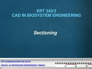
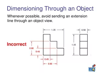
OBSERVER. ASSUME UPPER PART REMOVED. SECTON PLANE IN FV. ASSUME LOWER PART REMOVED. SECTON PLANE IN TV. OBSERVER. SECTIONING A SOLID. An object ( here a solid ) is cut by some imaginary cutting plane to understand internal details of that object.

E N D
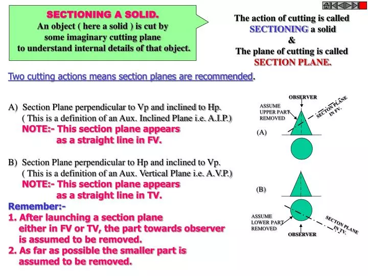
OBSERVER ASSUME UPPER PART REMOVED SECTON PLANE IN FV. ASSUME LOWER PART REMOVED SECTON PLANE IN TV. OBSERVER SECTIONING A SOLID. An object ( here a solid ) is cut by some imaginary cutting plane to understand internal details of that object. The action of cutting is called SECTIONING a solid & The plane of cutting is called SECTION PLANE. Two cutting actions means section planes are recommended. A) Section Plane perpendicular to Vp and inclined to Hp. ( This is a definition of an Aux. Inclined Plane i.e. A.I.P.) NOTE:- This section plane appears as a straight line in FV. B) Section Plane perpendicular to Hp and inclined to Vp. ( This is a definition of an Aux. Vertical Plane i.e. A.V.P.) NOTE:- This section plane appears as a straight line in TV. Remember:- 1. After launching a section plane either in FV or TV, the part towards observer is assumed to be removed. 2. As far as possible the smaller part is assumed to be removed. (A) (B)
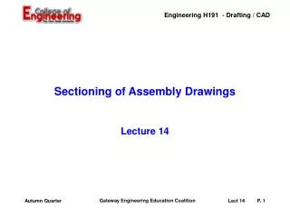
DEVELOPMENT OF SURFACES OF SOLIDS. MEANING:- ASSUME OBJECT HOLLOW AND MADE-UP OF THIN SHEET. CUT OPEN IT FROM ONE SIDE AND UNFOLD THE SHEET COMPLETELY. THEN THE SHAPE OF THAT UNFOLDED SHEET IS CALLED DEVELOPMENT OF LATERLAL SUEFACES OF THAT OBJECT OR SOLID. LATERLAL SURFACE IS THE SURFACE EXCLUDING SOLID’S TOP & BASE. ENGINEERING APLICATION: THERE ARE SO MANY PRODUCTS OR OBJECTS WHICH ARE DIFFICULT TO MANUFACTURE BY CONVENTIONAL MANUFACTURING PROCESSES, BECAUSE OF THEIR SHAPES AND SIZES. THOSE ARE FABRICATED IN SHEET METAL INDUSTRY BY USING DEVELOPMENT TECHNIQUE. THERE IS A VAST RANGE OF SUCH OBJECTS. EXAMPLES:- Boiler Shells & chimneys, Pressure Vessels, Shovels, Trays, Boxes & Cartons, Feeding Hoppers, Large Pipe sections, Body & Parts of automotives, Ships, Aeroplanes and many more. WHAT IS OUR OBJECTIVE IN THIS TOPIC ? To learn methods of development of surfaces of different solids, their sections and frustums. 1. Development is different drawing than PROJECTIONS. 2. It is a shape showing AREA, means it’s a 2-D plain drawing. 3. Hence all dimensions of it must be TRUE dimensions. 4. As it is representing shape of an un-folded sheet, no edges can remain hidden And hence DOTTED LINES are never shown on development. But before going ahead, note following Important points. Study illustrations given on next page carefully.
Development of lateral surfaces of different solids. (Lateral surface is the surface excluding top & base) = H L D R + 3600 D L R=Base circle radius. L=Slant height. H S S S S Cylinder: A Rectangle Pyramids: (No.of triangles) Cone: (Sector of circle) L H= Height D= base diameter Prisms: No.of Rectangles L= Slant edge. S = Edge of base H= Height S = Edge of base Cube: Six Squares. Tetrahedron: Four Equilateral Triangles All sides equal in length
FRUSTUMS = R + 3600 L L L L1 L1 STUDY NEXT NINE PROBLEMS OF SECTIONS & DEVELOPMENT DEVELOPMENT OF FRUSTUM OF CONE DEVELOPMENT OF FRUSTUM OF SQUARE PYRAMID Base side Top side R= Base circle radius of cone L= Slant height of cone L1 = Slant height of cut part. L= Slant edge of pyramid L1 = Slant edge of cut part.
Problem 1: A pentagonal prism , 30 mm base side & 50 mm axis is standing on Hp on it’s base whose one side is perpendicular to Vp. It is cut by a section plane 450 inclined to Hp, through mid point of axis. Draw Fv, sec.Tv & sec. Side view. Also draw true shape of section and Development of surface of remaining solid. Solution Steps:for sectional views: Draw three views of standing prism. Locate sec.plane in Fv as described. Project points where edges are getting Cut on Tv & Sv as shown in illustration. Join those points in sequence and show Section lines in it. Make remaining part of solid dark. C B D Y1 A A B C D E A E d” c” X1 b” e” a” e d For True Shape: Draw x1y1 // to sec. plane Draw projectors on it from cut points. Mark distances of points of Sectioned part from Tv, on above projectors from x1y1 and join in sequence. Draw section lines in it. It is required true shape. a For Development: Draw development of entire solid. Name from cut-open edge I.e. A. in sequence as shown. Mark the cut points on respective edges. Join them in sequence in st. lines. Make existing parts dev.dark. c b TRUE SHAPE a’ b’ e’ c’ d’ X Y DEVELOPMENT
Problem 2: A cone, 50 mm base diameter and 70 mm axis is standing on it’s base on Hp. It cut by a section plane 450 inclined to Hp through base end of end generator.Draw projections, sectional views, true shape of section and development of surfaces of remaining solid. Solution Steps:for sectional views: Draw three views of standing cone. Locate sec.plane in Fv as described. Project points where generators are getting Cut on Tv & Sv as shown in illustration.Join those points in sequence and show Section lines in it. Make remaining part of solid dark. Y1 X1 e’ a’ h’ b’ c’ g’ f’ d’ g h f For True Shape: Draw x1y1 // to sec. plane Draw projectors on it from cut points. Mark distances of points of Sectioned part from Tv, on above projectors from x1y1 and join in sequence. Draw section lines in it. It is required true shape. a e For Development: Draw development of entire solid. Name from cut-open edge i.e. A. in sequence as shown.Mark the cut points on respective edges. Join them in sequence in curvature. Make existing parts dev.dark. b d c TRUE SHAPE OF SECTION A SECTIONAL S.V B o’ SECTION PLANE DEVELOPMENT C D E X Y g” h”f” a”e” b”d” c” F G H A SECTIONAL T.V
Problem 3: A cone 40mm diameter and 50 mm axis is resting on one generator on Hp( lying on Hp) which is // to Vp.. Draw it’s projections.It is cut by a horizontal section plane through it’s base center. Draw sectional TV, development of the surface of the remaining part of cone. A B C a’ e’ c’g’ h’b’ d’f’ D a’ h’ b’ c’ g’ f’ e’ d’ E g1 g h f1 h1 F f G a e1 a1 o1 e O H b1 d1 b d A c c1 Follow similar solution steps for Sec.views - True shape – Development as per previous problem! DEVELOPMENT o’ HORIZONTAL SECTION PLANE Y X o’ O SECTIONAL T.V (SHOWING TRUE SHAPE OF SECTION)
SOME ACTUAL OBJECTS ARE SHOWN, SHOWING CURVES OF INTERSECTIONS. BY WHITE ARROWS. A machine component having two intersecting cylindrical surfaces with the axis at acute angle to each other. Intersection of a Cylindrical main and Branch Pipe. An Industrial Dust collector. Intersection of two cylinders. Pump lid having shape of a hexagonal Prism and Hemi-sphere intersecting each other. Two Cylindrical surfaces. A Feeding Hopper In industry. Forged End of a Connecting Rod.