Download
1 / 64
790 likes | 1.03k Vues
TRACK DRAINAGE (FOR RVNL ENGINEERS). TOPICS TO BE COVERED EFFECT OF DRAINAGE ON BALLAST WHAT IS BALLAST FUNCTION OF BALLAST DRAINAGE DEFINITION OF STATION YARD EFFECT OF IMPROPER DRAINAGE IN YARD . IMPORTANT POINTS ON DESIGN OF DRAINAGE IN YARD. What is Ballast.

E N D
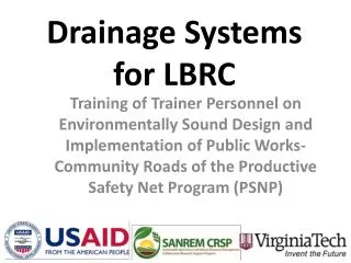
TRACK DRAINAGE (FOR RVNL ENGINEERS)
TOPICS TO BE COVERED EFFECT OF DRAINAGE ON BALLAST WHAT IS BALLAST FUNCTION OF BALLAST DRAINAGE DEFINITION OF STATION YARD EFFECT OF IMPROPER DRAINAGE IN YARD. IMPORTANT POINTS ON DESIGN OF DRAINAGE IN YARD.
What is Ballast • Ballast is the select crushed granular material placed as the top layer of the substructure in which the sleepers are embedded. • AS PER PARA 261/IRPWM stone ballast shall be used on all lines including points and crossing.
TRACK STRUCTURE CESS TRACK STR. B A L L A S T TRACK-FOUNDATION BLANKET FORMATION SUB - GRADE SUB - SOIL
Important Functions of Ballast • Resist vertical, lateral and longitudinal forces • Provide resilience and absorb energy • Reduce formation pressure • Facilitate track geometry correction • Facilitate track drainage • Provide voids
Additional Functions of Ballast • Inhibit vegetation growth • Absorb airborne noise • Provide adequate electrical resistance
Requirements of Track Ballast • Tough and wear resistant • Hard without getting crushed under moving loads • Generally cubical having sharp edge • Non-porous and non-absorbent of water
Requirements of Track Ballast • Resist Attrition (ghisai) • Durable and should not get pulverized under weather condition • Good drainage of water • Economical in cost
Track Ballast Ballast may be subdivided into following zones: • Crib • Shoulder • Top Ballast • Bottom Ballast
Ballast Fouling Potential sources are • Ballast breakdown • Handling • Tamping/packing • Traffic • Weathering CONTD..
Ballast Fouling • Fines from subgrade • Mud pumping • Seepage • Fines from surface • Droppings from trains • Wind or water transported
Effects of Fouling • Impedes drainage • Affects elasticity of ballast • Tamping/ packing becomes difficult • Increases dynamic loads • Reduces electrical resistance
Remedial measures - fouling • Shoulder screening : Preventive maintenance – Once in 3 yrs. • Deep Screening : Breakdown maintenance – Once in 10 yrs.
YARD DRAINAGE DEFENITION OF YARD: (AS PER CHAPTER II OF SCHEDULE OF DIMENSIONS.) • ON SINGLE LINE TO A DISTANCE OF 50 METRE BEYOND OUTER MOST POINTS AT EITHER END OF STATION. • ON DOUBLE LINE WHERE MULTI ASPECT / TWO ASPECT SIGNALLING IT IS CONSIDERED A DISTANCE BEYOND 50 METRE BEYOND OUTER MOST POINTS AT EITHER END OF STATION OR WHERE THERE IS NO LOOP LINE LAST STOP SIGNAL AT EACH LINE/ BLOCK SECTION LIMIT BOARD TO LAST STOP SIGNAL.
DRAINAGE MEANS... • Drainage means the interception , collection and disposal of water from, upon and under the track. In ballast bed, drainage of track essentially means the arrangement to drain out monsoon water getting accumulated in track foundation.
Why drainage • Without adequate track drainage, track formation may become saturated leading to weakening and subsequent failure. • Formation failure may be indicated by any of the following; mud pumping up through the ballast, repeated top and line problems, bog holes, or heaving of the formation. • Track drainage consists of two types: • − Surface drainage • − Subsurface drainage.
Surface drainage • Surface drainage removes surface runoff before it enters the track structure, as well as collecting water percolating out of the track structure. • Basic grading of the ground on either side of the track is a form of surface drainage, and allows water flowing out of the track structure to be removed. • Shoulder grading may be used in very flat areas where it is difficult to get sufficient fall for either surface or subsurface drains. • three main types of surface drainage. • (1) Cess drains. (2) Catch drains (3) Mitre drains.
Cess drains Cess drains are surface drains located at formation level at the side of tracks, to remove water that has percolated through the ballast and is flowing along the capping layer towards the outside of the track formation. Note: 1) Mitre drains are connected to cess and catch drains to provide an escape for water from these drains. 2)Mitre drains should be provided at regular intervals to remove water before it slows down and starts to deposit any sediment that it may be carrying. (shown in fig.2)
Cess drains Cess drains are most frequently found in cuttings where water running off the formation cannot freely drain away Surface drains can be constructed on fairly flat grades, as they are easily cleared of any sediment that may collect in them.
Cess drains Surface drains can be constructed on fairly flat grades, as they are easily cleared of any sediment that may collect in them. Cess drains are primarily intended for the protection of the formation by keeping the formation dry
Catch drains(also known as top drains) The purpose is to intercept overland flow or runoff before it reaches the track. Reduce the possibility of causing damage to the track or related structures, such as cuttings or embankments. Generally located on the uphill side of a cutting to catch water flowing down the hill and remove it prior to reaching the cutting. If this water was allowed to flow over the cutting face, it may cause excessive erosion and subsequent silting up of cess drains. Catch drains may be used alongside tracks that cut across a slight downhill grade
Subsurface drainage • Subsurface drainage is necessary for maintaining the integrity of the track formation and ensuring the stability of earth slopes. • Subsurface drainage is used for: • − drainage of the track structure − controlling of ground water • − the draining of slopes. • Subsurface drainage shall be provided in locations where the water table is at or near earthworks level. Subsurface drainage shall be provided along the cess, between, across, or under tracks as required.
Sub surface drainage • Subsurface drainage systems shall be designed to take surface runoff, ground water and seepage, and water collected from other drainage systems to which the new system is being connected. • Most systems will only have to cater for surface runoff. • If a drainage system is required to remove ground water and seepage, a detailed hydrological and Geotechnical investigation is required to determine the volume of water for the sizing of drains.
Subsurface drains are used where adequate surface drainage cannot be provided due to some restriction or lack of available fall due to outlet restrictions. • Following Subsurface drainage systems classified as per perform of their functions:
Collector drains • Collection of infiltration water that seeps into the formation (capping layer), as shown in Figure 6.
Drain for lowering water table • Draw-down or lowering of the watertable, as illustrated in Figure 7.
Interception drains • Interception or cut-off of water seepage along an impervious boundary.
Seepage drains • Drainage of local seepage such as spring inflow.
Horizontal and vertical drainage Horizontal and vertical drains are more specialized and are seldom used for track drainage. Horizontal drains are generally used to drain wet soils and speed consolidation of earth structures. Vertical drains may also be used to speed consolidation. Another type of vertical drain is used to drain water from behind retaining walls or bridge abutments.
Aggregate drains These drains consist of permeable granular material. The aggregate should be coarse enough to be free draining, but not so coarse as to allow the migration of fines into or through the permeable material. The graded aggregate is to be wrapped in a geotextile (Figure 14).
Pipe drains These consist of perforated or slotted pipes, installed by trenching and backfilling. Some type of filter material around the pipe or permeable backfill is normally required to minimise clogging of the drain perforations or slots
Pipe drains These consist of perforated or slotted pipes, installed by trenching and backfilling. Some type of filter material around the pipe or permeable backfill is normally required to minimise clogging of the drain perforations or slots
Pipe drains These consist of perforated or slotted pipes, installed by trenching and backfilling. Some type of filter material around the pipe or permeable backfill is normally required to minimise clogging of the drain perforations or slots
Geotextile Drains A geotextile drain may be a horizontal, vertical, or inclined blanket whose purpose is to collect subsurface water and convey it along the plain of the fabric to an outlet. The drain must also act as a filter to keep soil particles out of pores and prevent clogging. An example is shown in Figure 18.
Other arrangements • Where large volumes of water may need to be removed by subsurface drains, a carrier pipe may be used in conjunction with a collector drain, as shown in Figure 19. in next slide • With this arrangement the collector drain does not need to carry all the water. • The advantage of this arrangement is that excess (large volumes) water is removed from the collector drain thus preventing it seeping into the subgrade again at a point further down the drainage route.
Collector Drains Figure 19 shows a typical arrangement for a collector drain and carrier pipe located between two tracks. The subsurface water is collected by the collector drain between the two sumps shown, it is then conveys water to the down stream sump where it can enter the carrier pipe and be removed without any risk of it re-entering the subgrade.
Inlet/outlets for sub surface drains • The main purpose of inlet and outlet protectors is to reduce erosion. Where outlet velocities are expected to be high, some form of energy dissipater should be installed. Also, where the sediment load of the water being discharged from a drainage system is high, a silt trap should be installed