Download
1 / 42
480 likes | 866 Vues
Brake-by-Steer Concept. Steer-by-wire application with independently actuated wheels used for stopping a vehicle. Master Thesis Presentation Department of Precision and Microsystems Engineering. Bas Jansen 25-03-2010. Content. Introduction SKF Drive-by-wire Brake-by-steer concept

E N D
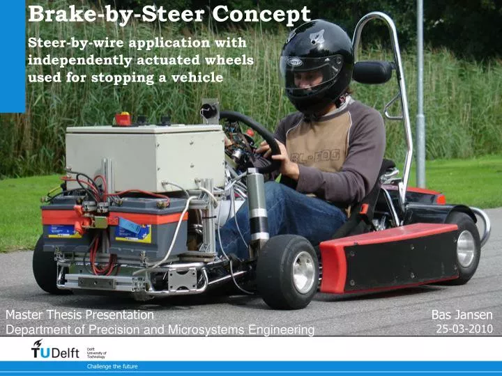
Brake-by-Steer Concept Steer-by-wire application with independently actuated wheels used for stopping a vehicle Master Thesis Presentation Department of Precision and Microsystems Engineering Bas Jansen 25-03-2010
Content Introduction SKF Drive-by-wire Brake-by-steer concept Modeling the Brake-by-Steer system Tire model Vehicle model Brake-by-steer cases Implementation on a Go-Kart Go-kart introduction Design Implementations Test Results Braking performance Lateral behavior Conclusion & Recommendations
1. Introduction
Introduction SKF - Svenska Kullagerfabriken AB
Introduction SKF - Svenska Kullagerfabriken AB SKF European Research Centre Nieuwegein
Introduction Conventional steering system Steer-by-wire with independently actuated wheels Steering wheel What is Steer-by-Wire Steering shaft Rack & Pinion Data transport Steering Controller Sensor & actuator Sensor & actuator
Introduction Replace hydraulic brake system with an individually electrically actuated brake system What is Brake-by-Wire Electro mechanical brakingactuators Data transport Brakingcontroller Brake pedal & sensor
Introduction Why By-Wire Modular design provides design freedom, reduces weight and requires less space Personalized and adaptive driving experience by varying control settings Increased safety potential in combination with intelligent vehicle safety systems
Introduction Safety challenge for By-Wire Primary systems with redundant back-up systems Increase safety level: • Implemented redundant components • Assign secondary function to initial primary function of a sub system • Steer by uneven distributed brake force • Brake-by-steer concept
Introduction Research Question: Is it possible to stop a vehicle with the brake-by-steer concept and how does this influence the steering controllability? Brake-by-Steer concept Position the front wheels such that they generate a braking force
2. Modeling the Brake-by-Steer system
Brake-by-Steer Modeling Model build-up: Tire model Vehicle (kart) model Brake-by-Steer cases Model construction m, I Length Width
Brake-by-Steer Modeling Tire behavior: No resistance force in longitudinal direction (x) Resistance force in lateral direction (y) Slip angle: The angle between tire’s direction of travel (V) and the direction towards which it is pointing (x) Tire modeling
Brake-by-Steer Modeling Tire modeling Lateral Tire Force C Slip angle
Brake-by-Steer Modeling Vehicle Model Vehicle equations of motion m, I Tricycle model
Brake-by-Steer Modeling Brake-by-Steer cases Steady state straight line driving brake force Toe-out Toe-out Steering angle Right Brake force [N] Toe-in Toe-in Steering angle Left
Brake-by-Steer Modeling Effect of longitudinal vehicle force for vehicle heading Toe-in steer to the right Toe-out steer to the right Steering to the right results in vehicle moment to the left Steering to the right results in vehicle moment to the right
Brake-by-Steer Modeling Effect of lateral vehicle force for vehicle heading Toe-in steer to the right Toe-out steer to the right Steering to the right results in lateral vehicle force to the left Steering to the right results in lateral vehicle force to the left
Brake-by-Steer Modeling Theoretical Results – Lateral Behavior Toe-out Symmetric toe equilibrium Asymmetric toe equilibrium There is no asymmetric toe-out equilibrium line Steering angle Right Summation Lateral Vehicle Force [N] Toe-in Steering angle Left
3. Implementation on a Go-Kart
Implementation on a Go-Kart Go-Kart Introduction Caster angle Kingpin inclination Remove mechanical linkage Caster angle • Kart specific features: • No individual wheel suspension • Flexible tube frame acts as suspension • Fixed rear axle • Caster angle and kingpin inclination Rotational path Left tire side view
Implementation on a Go-Kart Electromechanical Modifications Steering Wheel Toe handle • Absolute magnetic encoder measures steering angle • DC motor provides force feedback sense • Toe levers measure toe angle setpoints Steering wheel actuator Steering wheel angle sensor Steering shaft
Implementation on a Go-Kart Electromechanical Modifications Wheels Extension brackets • DC motor positions the wheels • Encoder used as control position signal • Absolute angle sensor used homing during initialization Motor + gear Encoders Absolute angle sensor Stub axle
Implementation on a Go-Kart Control algorithm Toe mode selection +/- C Controller Force Motor currents K Force feedback to steering wheel Feedback position control for wheel positions
Implementation on a Go-Kart Control algorithm Toe mode selection K 0 +/- C Controller Mimic steering torque with speed dependent return to center torque Feedback position control for wheel positions
Implementation on a Go-Kart Implemented design Steering wheel actuation Electronics Velocity sensor Batteries Left wheel actuation
4. Test Cases and Results
Test cases & Results Braking performance of the brake-by-steer concept Lateral vehicle behavior during brake-by-steer maneuver Test cases Test track at SKF ERC Nieuwegein
Test cases & Results Results – Braking Performance Theoretical maximum: 1.5 kN
Test cases & Results Slip angles Results – Lateral behavior Calculated driven path for symmetric toe-in (30º) with steering offset of 2, 4, 6, 8 degrees to the right Velocities
Test cases & Results Slip angles Results – Lateral behavior Calculated driven path for symmetric toe-out (60º) with steering offset of 2, 4, 6, 8 degrees to the right Velocities
5. Conclusions & Recommendations
Conclusions & Recommendations Brake-by-steer concept can back-up failing brakes with a reduced braking performance (~50%). Lateral behavior changes drastically and ranges of inverted steering occur. These make the vehicle uncontrollable for the driver. Conclusions Brake-by-Steer Concept
Brake-by-Steer Modeling Conclusions Toe-modes Theory and practice differ on effectiveness of toe modes due to due to caster angle and kingpin inclination induced roll motion. The kart tire that is turned out the most gains vertical axle load and dictates the lateral behavior of the vehicle.
Conclusions & Recommendations Recommendations Brake-by-Steer Concept Before the brake-by-steer concept can be applied in cars, the relation between steering angle and vehicle heading must be restored. Calculate how to position the wheels to generate a brake force and follow expected steering input according toe strategy. Steering angle Brake pedal Controller Wheel actuators To create this model the presented conceptual model needs to be extended and validated on a car in stead of a go-kart
Thank you for your attention Questions?
Implementation on a Go-Kart Steering system design requirements Angle sensor Straingages • Performance requirements: • Wheel steering rate typical 80 º/s • Steering frequency typical 1 Hz (amp = ~10 deg) • Steering torque at wheels • Nominal 8 Nm • Peak 50 Nm • Measured braking performance • Braking Force 1,2 kN Velocity sensor
Brake-by-Steer Modeling Brake-by-Steer cases – Vehicle controllability A0 A1 A1 Lateral Vehicle Force [N] B0 B1 Slip angle Inverted steering occurs at symmetric toe mode for >
BACKUP Siemens VDO eCorner The hub motor (2) is located inside the wheel rim (1). The electronic wedge brake (3) uses pads driven by electric motors. An active suspension (4) and electronic steering (5) replace conventional hydraulic systems.