Download
1 / 19
190 likes | 194 Vues
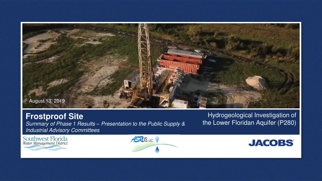
August 13, 2019. Hydrogeological Investigation of the Lower Floridan Aquifer (P280). Frostproof Site. Summary of Phase 1 Results – Presentation to the Public Supply & Industrial Advisory Committees. AGENDA. Introduction and Background Phase 1 Purpose and Objectives

E N D
August 13, 2019 Hydrogeological Investigation of the Lower Floridan Aquifer (P280) Frostproof Site Summary of Phase 1 Results – Presentation to the Public Supply & Industrial Advisory Committees
AGENDA • Introduction and Background • Phase 1 • Purpose and Objectives • Phase 1 Drilling and Testing Program • Phase 1 Results • Lithology • Groundwater Elevations • Water Quality • Hydraulic Parameters • Monitoring Well Installation • Next Steps 2
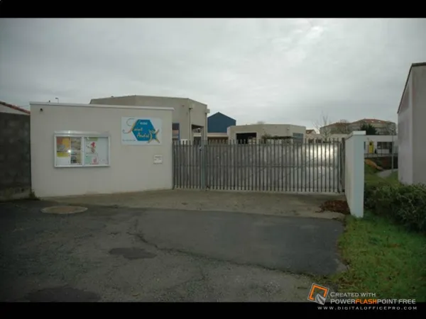
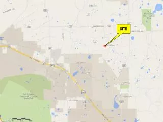
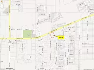
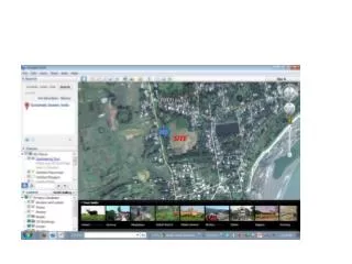
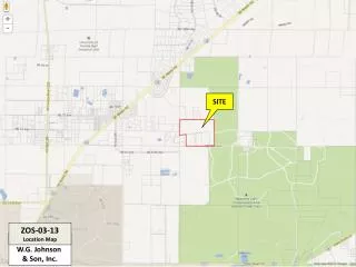
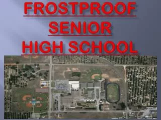
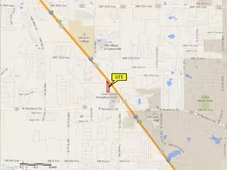
INTRODUCTION • Frostproof Site • One of three P280 LFA well drilling sites • Southern most site • Near Frostproof, FL 3
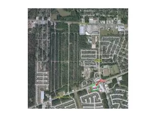
BACKGROUND HYDROGEOLOGY Approximate project location 5
Phase 1— Purpose & Objectives • Raw Water Production • Determine if the LFA can support future brackish water supply • Confinement • Determine if there is sufficient confinement between UFA/LFA • Concentrate Disposal • Determine if the LFA could support future injection wells for membrane concentrate disposal 6
Phase 1—Drilling & Testing Program • Monitoring Well Installation • Surficial aquifer (SAMW-1) • Upper Floridan aquifer (UFAMW-1) • Drilling • Drill to sub-Floridan confinement • Continuous lithologic sampling • Cores at four discrete depths • Groundwater Elevations • Geophysical and OBI Logging • Hydraulic and Water Quality Data • Incrementally during drilling • Packer Testing • 7 discrete depths • LFA Monitoring Well Completion • Dual zone monitoring, LFAI, LFAII(a) • Constant Rate Aquifer Tests • Water quality sampling 7
Phase 1—Groundwater Elevation (ft NAVD88) Intermediate casing installation Note: GWEs not corrected for salinity 10
Phase 1—Groundwater Elevation (ft NAVD88) Depth of Drilled Pilot Hole (ft bgs) <0.5 ft Note: GWEs not corrected for salinity Intermediate casing installation 11
UFA/LFA Groundwater Elevation Difference Note: GWEs not corrected for salinity Phase 1 Results—Vertical Flow Gradients • Graphic plots MZMW-1 GWE – UFAMW-1 GWE • Negative difference = downward vertical gradient • LFAI groundwater elevations similar to UFA groundwater elevations • Downward gradient after intermediate casing set • Interflow in the borehole affected water quality results Intermediate casing 12
MZMW-1 Drill Stem Water Quality Phase 1 Results—Water Quality • Downward flow in the borehole affected water quality results • Little variation observed between LFAII(a) and LFAII(b) due to intermixing • LFAII • Chloride ~70 mg/L • Sulfate ~ 1,800 mg/L • TDS ~ 3,000 mg/L Intermediate casing 13
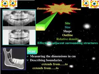
Phase 1 Results—Geophysics with Tentative Hydrogeologic Picks 14
Phase 1— Remaining Testing • LFA Monitoring Well Completion • Dual zone monitoring • Constant Rate Aquifer Tests • Pumping rate: ~200 – 500 gpm • LFA I • LFA II(a) • Monitoring zones: SA, UFA, LFA I, LFA II(a) • Water quality: primary, secondary, RO analytes • Lab permeabilities on core 16
Phase 1—Conclusions Water Supply Concentrate Disposal • Production zone in LFA II(a) • 3 gpm/ft, estimated • UFA/LFA confinement was identified • >500 ft thickness • Packer testing and flow compilation log suggest good confinement • No effects observed in UFA during testing program • Injection zone in LFA II(b) • 6 gpm/ft, estimated • Confinement between LFA II(a) and LFAII(b) • ~300 ft thickness • Geophysical logs suggest two distinct flow zones separated by confining interval 17
Next Steps at Crooked Lake/Frostproof/Lake Wales Crooked Lake • Construction on-going with dual zone LFA monitoring well Frostproof • Complete Phase 1 • Just kicked-off Phase 2 Lake Wales • Construction on-going with Phase 1 (similar to Frostproof testing) 18
Phase 1 Results—Lithology and Tentative Hydrogeologic Picks 600 9