Download

1 / 23
240 likes | 342 Vues
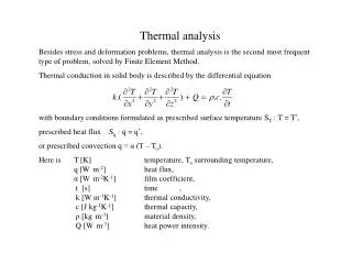
Thermal Design And Analysis. Stephen Smee smee@jhu.edu (410) 516-7097. Thermal Requirements and Considerations. Three thermal regimes: Ambient, 200K, and 77K 200K and 77K regimes cooled by LN 2 Detector cooldown rate ≤ 0.1 K/min (300K 77K takes 37hrs). Ambient (268K < T < 300K). 77K.

E N D
Thermal Design And Analysis Stephen Smee smee@jhu.edu (410) 516-7097
Thermal Requirements and Considerations • Three thermal regimes: Ambient, 200K, and 77K • 200K and 77K regimes cooled by LN2 • Detector cooldown rate ≤ 0.1 K/min (300K 77K takes 37hrs) Ambient (268K < T < 300K) 77K 200K 2
Analysis Objectives • Determine system temperatures • Estimate system heat load • Estimate cooldown time • Determine window temperature and thermal gradients Ambient (268K < T < 300K) 200K 195K 77K Camera Module Focal Plane Assm. Field Lens 3
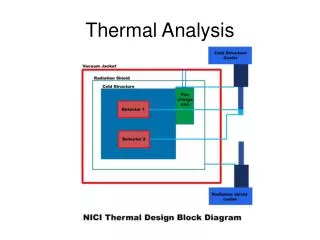
Thermal Management Strategy • Two dewars • One to cool the radiation shields (autofilled) • One to cool the focal plane mechanisms (manual fill) • Use thermal resistor to achieve 200K shield temperature • Subcool slightly to facilitate camera module temperature control Vessel & Window T = Ambient 77K Radiation Shield Thermal Resistor 200K q r = 420 mm Detector Dewar 200K Radiation Shield Shield Dewar 4
Thermal Modeling Strategy • Develop accurate analytical and FEA submodels for key assemblies • Window, Camera Module, flexures, etc. • Evaluate submodels • Temperature profiles, thermal resistance, etc. • Use results from submodels to create simplified, compact models for system level analysis • Feed results from submodels and system model back into the thermal/mechanical design 5
Window Thermal Analysis • Objectives: • Determine lens radial temperature profile • Determine heat load Ambient Temp. qrad qcon = .9 qrad = .9 Baffles = .03 200K Heat sink 6
Window Model Details • Axisymmetric model • Baffle diameter scaled to area of square opening • Steady State, coupled conduction/radiation model • Conduction to lenses only considered at the lens-seat interfaces • Scale • L1: 15” diameter, 2.13” thick • L2: 15” diameter, 1.58” thick • Materials • Lenses: Fused Silica, k = 1.38 W/mK • Barrel and Cell Material: 6061-T6, k = 165 W/mK • Ambient temperature range: 268K < T < 300K, 285K (nominal) • Lenses assumed to be black, = 0.9 • = 0.03 assumed for low emissivity surfaces • FEA Software: ABAQUS 7
Temperature Profiles: 268K ambient (lower limit) 263.9K 268K 263.3K 252.2K 250.5K 259.9K qrad = 7.0 W 8
Temperature Profiles: 285K ambient (nominal case) 279.1K 285K 278.1K 265.0K 273.9K 262.1K qrad = 9.5 W 9
Temperature Profiles: 300K ambient (upper limit) 292.2K 300K 291.0K 275.7K 272.1K 286.4K qrad = 11.9 W 10
Camera Module Analysis • Objectives: • Determine cooldown time for the camera module • Develop compact model for system analysis • Investigate thermal gradients during cooldown 200K at t = 0 qrad = .9 qcon qcon qcon qrad = .9 qrad qrad qrad 285K at t = 0 11
Camera Module Model Details • Axisymmetric model • Transient, coupled conduction/radiation model • Materials • Lenses • CaF2: k = 9.7 W/mK, Cp(T) • S-FTM16: k = 0.947 W/mK, Cp(T) • Lens mounts • 6061-T6, k = 136 W/mK, Cp(T) • All radiating surfaces assumed black, = 0.9 • Initial conditions: • Vessel temp = 200K • Camera Module = 285K • FEA Software: ABAQUS 12
Camera Module Compact Model Detailed Model L4 Compact Model Reference Node 14
System Level Model • Determine: • Cooldown time • Steady state heat load for 268K, 285K, and 300K ambient • Required heat input to camera module Thermal Resistor (“Cold Clamp”) 285K qrad = .03 qheater qcon qcon = .9 qmount T = 270 K T = 77K 15
System Level FEA Model Details • Axisymmetric model • Baffle diameters scaled to area of square opening • Transient, coupled conduction/radiation model • Simple conductive paths calculated analytically; not included in (FEA model) • Radiating surfaces • = 0.9 assumed for black surfaces • = 0.03 assumed for low emissivity surfaces • Vacuum vessel • Held at ambient temperature • Low emissivity inner surface • Window • Represented by compact model with constant temperature as determined by FEA submodel 16
System Level FEA Model Details Cont. • Radiation shields • 10 mm thick, 6061-T6 • Low emissivityouter surfaces, black inner surfaces • Camera Module • Compact model used to simplify computation • Cooled by radiation only; black surfaces assumed • Heat flux applied to achieve 200K operating temperature • Approximately 4W comes from the mounts • Thermal resistor i.e. the “Cold Clamps” • Heat flow through the resistor adjusted to achieve camera module operating temperature (200K) • Focal plane mechanisms are not included in the system model • Mechanisms cool more quickly than the camera module 17
Steady State Thermal Profile: 268K Ambient Thermal Resistor Heat Flow 36 W 268K 177K 88K qheater = 12 W 196K 25 W 7 W 200K 255K qmount = 3 W 77K 18
Steady State Thermal Profile: 285K Ambient Thermal Resistor Heat Flow 37.5 W 285K 89K 182.5K qheater = 6.5 W 204K 33 W 9.5 W 200K 268K 77K qmount = 4 W 19
Steady State Thermal Profile: 300K Ambient Thermal Resistor Heat Flow 39 W 300K 90K 187K qheater = 1 W 213K 40.6 W 12 W 200K 279K qmount = 4.5 W 77K 20
Transient Results Heat flux applied to CM 21
Conclusions • Heat load over the anticipated operating temperature range is between approximately 51 W and 64 W • LN2 usage will be about 1.25 liters/hr • Cooldown time will be approximately 2 to 3 days • Set by the thermal mass of the 200K shield and camera module • System temperatures are in line with expectation • Thermal gradients are high in L2 but do not pose a problem optically • Temperature gradients in L3 – L6 are < 1K • A thermal resistor that flows approximately 40 W between the 77K and 200K radiation shields is necessary. 23