Download
1 / 30
300 likes | 457 Vues
Fixed Outline Multi-Bend Bus Driven Floorplanning. W. Sheng, S. Dong, Y. Wu and S. Goto Tsinghua University, Beijing. ISQED 2010. Outline. Introduction Problem Formulation Placement Constraints for Bus Algorithm Experimental Results Conclusion. Introduction.

E N D
Fixed Outline Multi-Bend Bus Driven Floorplanning W. Sheng, S. Dong, Y. Wu and S. Goto Tsinghua University, Beijing ISQED 2010
Outline • Introduction • Problem Formulation • Placement Constraints for Bus • Algorithm • Experimental Results • Conclusion
Introduction • Modern Hierarchical SOC design flows need to deal with fixed-outline floorplanning under the interconnect constraints • This paper integrates the bus routing issue into the floorplanning process, which handles hard blocks in a fixed-outline area for SOC designing
Introduction • By far, all the existed methods that were adopted to address the BDF problem are based on SA framework • With the help of a certain kind of topological representations • SA is a non-deterministic method, it always needs a great number of iterations to get the result • This paper re-visits the BDF problem and adopts a deterministic algorithm named Less Flexibility First • Without any topological representations
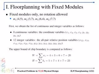
Problem Formulation • Input: • A set of rectangle blocks B={bi | i=0,1,…,n-1} • A set of m buses U={ui | i=0,1,…,m-1} and goes through a set of blocks BiB • The width W and height H of the chip, as the fixed-outline constraint • Output: • The position information of the n blocks and the m buses • The objective is to minimize the chip area and the total bus area
Problem Formulation • Assumptions: • All the blocks are hard ones • All the blocks in the test cases can be rotated or reflected during the packing process • All the bus bendings should occur at the blocks that are in the corresponding bus nets • There is no restriction on the shape of the bus and the number of bendings in the bus
Basic Concepts for LFF • Less Flexibility First (LFF) is a deterministic algorithm for block placement • It packs the blocks one by one during the floorplanning process • The most suitable block from the unpacked blocks is chosen and packed in every step • Which block is chosen in a step depends on its “flexibilities”
Basic Concepts for LFF • The basic idea of the LFF algorithm is packing the blocks from corners of the die gradually to the center • Choosing and packing one block is called a Packing Step • In every step, each unpacked block will be pseudo-placed at each existed corner, called Corner Packing Step (CPS) • If the placing is feasible, then it is a Candidate Corner Packing Step (CCPS) • The block pseudo-placed at the corner will not cause the overlap between this block and those already packed blocks
Basic Concepts for LFF • Each step has some CCPSs • The task of the LFF is to choose the best CCPS in every step • The quality of the CCPS is measured by flexibility • The flexibility of the empty space • (a) The flexibility of a corner packing is 3/8 • (b) The flexibility of a side packing is 5/8 • (c) The flexibility of a hollow space packing is 1
Basic Concepts for LFF • The flexibility of the to-be packed blocks • Ai, wi, hi are block i’s area, width and height • A, W, H are the given outline’s area, width and height
Basic Concepts for LFF • The flexibility of the packing position • ( x0 , y0 ) denotes the coordination of the center of the work space • ( xc , yc ) denotes the corresponding corner coordination of the CCPS
Basic Concepts for LFF • The flexibility of the buses • k is the number of the bus components that can be packed • li is the length of each bus component
Basic Concepts for LFF • The flexibility of the CCPS
Placement Constraints For Bus • Position Constraint
Placement Constraints For Bus • All the bus bendings should occur at the blocks that are in the corresponding bus nets • No-Overlapping Constraint • In a feasible BDF solution, no horizontal/vertical bus component overlaps any other horizontal/vertical bus components
Algorithm • Flexibility Modification • Redefine the flexibility of the to-be-packed blocks • TL is the total initial length of all the buses • Li is the initial length of the buses that pass through the block bi
Algorithm • Update the flexibility of the to-be-packed blocks after every packing step
Algorithm Implementation • Get All CCPSs In A Packing Step • In every packing step, each unpacked block will be pseudo-placed at each existed corner • (a) The block pseudo-placed at the corner will not cause the overlapping between this block and those already packed blocks • (b) There exist can-be-packed bus components that will connect this block to the corresponding buses
Algorithm Implementation • Get All CCPSs In A Packing Step • For (b), there are three cases: • Case 1. bi is the first to-be-packed block of the blocks in Bi • Case 2. bi is the second to-be-packed block of the blocks in Bi • Case 3. There are more than one blocks in Bi have been packed before bi
Algorithm Implementation • For case 3, suppose there are two blocks bj , bk in Bi have already been packed and the bus component between them is ui1, then this case can be divided into two cases: • Case 3.1 bi is connected to bj (bk) by bus ui2 , and ui1 and ui2 are both horizontal/vertical • Case 3.2 bi is connected to bj (bk) by bus ui2 , but the direction of ui2 is not the same as the direction of ui1
Algorithm Implementation • In case 3.1, ui1 and ui2 should be merged • Case 3.2 is the same as case 2, except that it will form a bending in the bus ui
Algorithm Implementation • Bus Overlapping Removal • If the to-be-packed bus component overlaps any packed bus component, adjust the position of the to-be-packed bus component until there is no overlapping • If the position adjustment doesn’t work, this CCPS will be discarded
Algorithm Implementation • Get The Best CCPS • According to the principle of Less Flexibility First, the best CCPS is from all the CCPSs with the smallest flexibility value • In every packing step, the best CCPS is selected, and the corresponding block and bus components are packed
Experimental Results • n100-c, dead space=5.72%, aspect ratio=1.0
Conclusion • This paper addresses the BDF problem in a fixed-outline area • By adding the placement constraints for buses to the LFF algorithm, their approach can generate a good BDF solution with small dead space percentage and short run time