Download
1 / 31
310 likes | 449 Vues
CS 630: Advanced Microcomputer Programming. Fall 2008 Professor Allan B. Cruse University of San Francisco. Course Synopsis. We study Intel-64 processor architecture It’s implemented in our Core-2 Quad CPU

E N D
CS 630: Advanced Microcomputer Programming Fall 2008 Professor Allan B. Cruse University of San Francisco
Course Synopsis • We study Intel-64 processor architecture • It’s implemented in our Core-2 Quad CPU • We pretend we’re using a ‘bare machine’ (i.e. no operating system to ‘hide’ what’s going on, just standard PC hardware and accompanying vendor-supplied firmware) • So we get to build our own miniature OS • Doing this will bring us face-to-face with the CPU’s most fundamental capabilities
Methodology • Our interactive computer classroom lets us take a ‘hands on’ approach to our studies (i.e., we combine ‘theory’ with ‘practice’) • Typically we’ll devote first part each class to a ‘lecture’ about aspects of x86 theory • Then we’ll take time in the second part of class for ‘laboratory exercises’ that put the newly learned ideas into ‘working code’
Course prerequisites • Experience with C / C++ programming • Familiarity with use of Linux / UNIX OS • Acquaintance with x86 assembly language • Knowledge of the x86 general registers • Awareness of the x86’s instruction-set • Understand the CPU’s fetch-execute cycle • Recall the ways memory is addressed
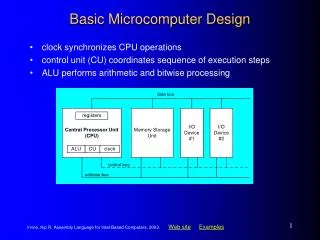
Simplified component diagram Central Processing Unit Main Memory system bus I/O device I/O device I/O device I/O device …
Review of the legacy x86 API CS EAX DS EBX ES ECX FS EDX GS ESI SS EDI Segment Registers (16-bits) EBP ESP EIP General Registers (32-bits) EFLAGS Program Control and Status Registers (32-bits)
Review of Instruction-Set • Data-transfer instructions (mov, xchg, …) • Control-transfer instructions (jmp, call, …) • Arithmetic/Logic instructions (add, or, …) • Shift/Rotate instructions (shr, rol, …) • String-manipulation instructions (movs, …) • Processor-control instructions (cli, hlt, …) • Floating-point instructions (fldpi, fmul, …)
Review “Fetch-Execute” Cycle main memory central processor Temporary Storage (STACK) ESP Program Variables (DATA) EAX EAX EAX EAX Program Instructions (TEXT) EIP the system bus
Steps in ‘Fetch-Execute Cycle’ Fetch next instruction Advance instruction-pointer Decode fetched instruction Execute decoded instruction INTR ? Interrupt Service Routine no yes
Review of operand addressing • Implicit addressing (e.g. pushf, cbw, scasb, cli, xlat, …) • Register addressing (e.g., mov %ax, %bx) • Direct addressing (e.g., incl salary, movw $0, counter, …) • Indirect addressing (e.g., add %dx, 0x14(%ebx, %esi, 2) )
Course Textbook • Tom Shanley, Protected Mode Software Architecture, Addison-Wesley (1996) Initial reading assignment: Week 1: Read Part One (Chapters 1-3) Week 2: Read Part Two (Chapters 4-5)
Instructor Contact Information • Office: Harney Science Center – 212 • Hours: Mon-Wed-Fri 12:30pm-1:15pm and Tues-Thurs 6:30pm-7:15pm • Phone: (415) 422-6562 • Email: cruse@usfca.edu • Webpage: <http://cs.usfca.edu/~cruse>
CPU Execution Modes POWER-ON / RESET REAL MODE PROTECTED MODE VIRTUAL 8086 MODE SYSTEM MANAGEMENT MODE
The ‘pre-boot’ environment • None of the normal library functions • No graphical desktop, no file-system • No editors, compilers, debuggers • No network-access, no mouse, no printer • Only one of the four processors is active • Only a tiny fraction of the system memory is accessible (only 1-MB, out of 4096-MB) • The method of addressing memory is very different from what we’re accustomed to!
64KB Memory-Segments • Fixed-size segments (can be overlapping) • Segments start on paragraph boundaries • Segment-registers serve as “selectors” stack data SS DS code CS
Real-Mode Address-Translation 16-bit segment-address 16-bit offset-address 0x1234 0x6789 Logical address: 0x12340 + 0x06789 ---------------- 0x18AC9 x 16 + 20-bit bus-address 0x18AC9 Physical address:
Using ROM-BIOS functions • Our system firmware provides many basic service-functions that real mode programs can invoke (this includes ‘boot-loaders’): • Video display functions • Keyboard input functions • Disk access functions • System query functions • A machine ‘re-boot’ function
A valuable Online Reference • Professor Ralf Brown’s Interrupt List (see webpage link under ‘Resources’) • It tells how to make BIOS system-calls, to perform numerous low-level services from within Real-Mode 8086 applications (such as ‘boot loader’ programs)
Power-On CS:IP ROM-BIOS Expansion ROMs Video BIOS VRAM DRAM 1-MB uninitialized memory area
System setup ROM-BIOS CS:IP Expansion ROMs Video BIOS VRAM Extended BIOS Data Area DRAM EBDA 1-MB ROM-BIOS DATA AREA Interrupt Vector Table RBDA IVT
Bootstrap Loader ROM-BIOS Expansion ROMs Video BIOS VRAM Extended BIOS Data Area DRAM EBDA 1-MB CS:IP BOOT_LOCN ROM-BIOS DATA AREA Interrupt Vector Table RBDA Disk Storage IVT
A very short example // smile.s .section .text # our linker needs this name mov $0x0E, %ah # BIOS function-selector mov $0x01, %al # character-glyph selector mov $0x00, %bh # display-page selector int $0x10 # invoke ROM-BIOS service freeze: jmp freeze # enter an infinite loop .org 510 # offset to boot-signature .byte 0x55, 0xAA # value for boot-signature ,end # nothing more to assemble
Assemble, link, and install # Use the GNU/linux assembler to translate source-code to object-code: $ as smile.s -o smile.o # Use the GNU/Linux linker to convert object-code to binary-format: $ ld smile.o -T ldscript -o smile.b # NOTE: This linking step requires using a special ‘linker-script’ in order # to override the default ELF-format output-file (the customary format of # a file that the Linux operating system knows how to load and execute) # Copy the binary-executable to the place on our CS630 disk-partition # where the GRUB boot-loader will expect to find it: $ dd if=smile.b of=/dev/sda4
Our ‘fileview’ utility • You can use the ‘fileview.cpp’ program (on our cs630 course-website) as a convenient tool for viewing files: $ ./fileview smile.b • Since ‘fileview’ also works with device-files (if you have the required read-permission), you can verify that ‘smile.b’ is successfully installed on our CS630 disk-partition: $ ./fileview /dev/sda4
Observations • Our ‘smile.s’ program-code does not make use of any assembly-language labels, nor does it use any instructions that would be differently translated for the ‘real-mode’ pre-boot execution environment than for the ‘protected-mode’ environment used by Linux application-programs • A few different coding-conventions would be needed when these conditions change
Example • Any assembly-language instruction that refers to a 16-bit (or to a 32-bit) register will need to be assembled differently for ‘real-mode’ execution • This is accomplished using the .code16 assembler directive: mov $0x1301, %ax # inserts an operand-size override prefix .code16 # needed for correct ‘real-mode’ execution mov $0x1301, %ax # omits the operation-size override prefix
Symbolic addresses • The linker assumes your code will reside in memory at an address-offset equal to 0, so it assigns address-values to all of your program-symbols accordingly • But the bootstrap-loader places your code at an address-offset equal to 0x7C00 ! • Thus you must perform a ‘renormalizing’ operation if you want to use your symbols
Example that uses symbols .code16 # for x86 ‘real-mode’ .section .text ljmp $0x07C0, $main # (this renormalize CS:IP) main: mov %cs, %ax # address program data mov %ax, %ds # with DS register mov %ax, %es # also ES register mov $msg, %bp # point ES:BP to string mov len, %cx # string-length into CX mov $0x0009, %bx # page and color in BX mov $0x0A28, %dx # row and column in DX mov $0x1301, %ax # ‘write_string’ function int $0x10 # invoke BIOS service freeze: jmp freeze # enter an infinite loop msg: .ascii “ Hello, world! \n” # text-message to display len: .short . – msg # length of the message
Effect of the long-jump BOOT_CODE BOOT_CODE IP = 0x0005 IP = 0x7C00 CS = 0x07C0 Now all the symbol offsets are correct, relative to segment register CS CS = 0x0000 AFTER… BEFORE…
In-class exercise #1 • Download the textfile ‘welcome.s’ from our class website into your own subdirectory: $ cp /home/web/cruse/cs630/welcome.s . • Then assemble it (use ‘as’), link it (use ‘ld’) and install it (use ‘dd’) on your hard disk’s partition • Reboot your computer, and select the GRUB menu-option which will ‘execute’ that code • Did you see the welcome-message? Were you able to ‘reboot’ by simply pressing a key?
In-class exercises #2, #3, #4 • Can you modify the ‘welcome’ message so that is will also include your name? Can you change the color from green to red? Can you make the message appear near the bottom of the console screen?