Download
1 / 1
10 likes | 101 Vues
L 20. L 00. Cavity-enhanced dipole forces for dark-field seeking atoms and molecules. David McGloin, Kishan Dholakia. Tim Freegarde. Dipartimento di Fisica, Università di Trento 38050 Povo (TN), Italy. J F Allen Physics Research Laboratories, University of St Andrews,

E N D
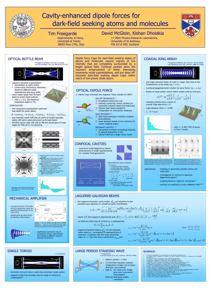
L20 L00 Cavity-enhanced dipole forces for dark-field seeking atoms and molecules David McGloin, Kishan Dholakia Tim Freegarde Dipartimento di Fisica, Università di Trento 38050 Povo (TN), Italy J F Allen Physics Research Laboratories, University of St Andrews, Fife KY16 9SS, Scotland OPTICAL BOTTLE BEAM Dipole force traps for dark-field seeking states of atoms and molecules require regions of low intensity that are completely surrounded by a bright optical field. Confocal cavities allow the resonant enhancement of these interesting transverse mode superpositions, and put deep off-resonant dark-field seeking dipole traps within reach of low-power diode lasers. COAXIAL RING ARRAY • Freegarde & Dholakia, Phys Rev A, in press • see Arlt & Padgett, Opt. Lett. 25 (2000) 191-193 • Freegarde & Dholakia, Opt. Commun. 201 99 (2002) • see Zemánek & Foot, Opt. Commun. 146 119 (1998) • use single Gaussian beam of waist w1 larger than that of the fundamental cavity mode (w0 = aw1) • counterpropagating beam smaller by same factor (w2 = aw0) • beams of equal power cancel where nodal surfaces intersect • Laguerre-Gaussian superposition: • cancellation at cavity centre • constructive interference elsewhere thanks to different radial dependences and Gouy shifts OPTICAL DIPOLE FORCE ( ) Jdipole traps eliminate the magnetic fields needed for MOTs1 • return beam larger than forward beam to avoid nodal surfaces æ ö w z 1 1 ( ) ç ÷ 2 = - r z ln 1 ( ) ç ÷ ( ) ( ) 0 2 2 FAR OFF RESONANCE2-5 Jbroadband interaction and Jminimal scattering, hence suitable for spectrally complex atoms and molecules Lintense laser beam needed to compensate for interaction weakness BLUE-DETUNED6-10 Jdark-field seeking to minimize residual perturbations Lneed isolated islands of low intensity for closed trapping region RESONANT CAVITIES11-13 Jcan greatly increase circulating intensity, as optical absorption is low Loptical field not a single cavity mode w z w z w z è ø • with = 0.5, the maximum modulation depth is 7%. 2 2 1 • intensity minima form a series of coaxial rings spaced by l/2 • traps deepest when a = 0.492 • r0 ~ 0.7 w0(z) COMPOSITION • five component superposition optimizes trap depth for given radius: towards high intensity • high = + - - - 0 . 691 0 . 332 0 . 165 0 . 332 0 . 525 E L L L L L 00 10 20 30 40 towards low intensity • trap intensity nearly half that at centre of simple Gaussian beam with same waist and power as forward beam • 99.99% mirrors with 100 mW at 780 nm would give 5 K trap depth for 85Rb at 0.2 nm detuning • low • with a = 0.492, 99% of power in first 5 modes CONFOCAL CAVITIES L/R2 • transverse mode degeneracy allows enhancement of mode superpositions for complex field geometries 1 confocal Intensity distribution within a perfectly confocal resonator. Above left: mean intensity shown for central 40% of the cavity. The solid lines show where the forward beam has fallen to e-2 of its on-axis intensity. Above: viewed on a wavelength scale around the cavity centre, the modulation due to interference between the counter-propagating beams is apparent. Here, l = 100 mm, = 780nm, = 2. Left: depth of modulation due to interference between forward and return beams. Black=0, white=100%. 0 1 L/R1 Intensity distribution around the centre of a confocal cavity.Dashed and solid lines indicate the nodal and antinodal planes; the dotted line shows where the lowest part of the trap wall is maximum. Logarithmic contours (four per decade) refer to the peak intensity on axis. l = 100 mm, l = 780 nm, a = 0.492. Intensity distribution when the cavity mirrors are 0.1 mm from their confocal separation (Dl/l = 0.001), for r2 = 0.99, t2 = 0.01. The nodal surfaces, shown dashed, are now curved, reflecting the increase in Gouy phase with mode number. Central and trapping intensities are reduced by about a third. • three different views of physics: RAY OPTICS • 2 round trips before repeating • inverted image after 1 round trip • returning beam forward beam Applications: • trapping of spectrally complex atoms and molecules • investigation of vortices in quantum degenerate gases14 • coupling between adjacent microtraps15 • cooling via coupling to cavity radiation field16-18 R2 R1 GAUSSIAN BEAMS HALF TRIP ROUND TRIP even odd even CAVITY MODES Cartesian i + j Hermite-Gaussian • half modes simultaneously resonant • (anti-)symmetric image = • superposition of even(odd) modes cylindrical 2p + |m| Laguerre-Gaussian Amplitudes ap0 of mode components forming the complete five-component optical bottle beam with =2. LAGUERRE-GAUSSIAN BEAMS MECHANICAL AMPLIFIER • the Laguerre-Gaussian cavity modes are solutions to the paraxial wave equation in cylindrical polar coordinates, col intensity • moving the mirrors from their confocal separation causes an amplified displacement of the trap centre • amplification by same factor as intensity enhancement ( ) ( ) ( ) m æ ö - + + æ ö æ ö 1 exp i 2 p m 1 tan z z 2 2 2 4 p ! 2 r 2 r r i kr ( ) trap centre intensity ç ÷ ç ÷ ç ÷ J = - - + J - R m r , z , L exp i m i kz L ( ) ç ÷ ç ÷ ( ) ( ) ( ) ç ÷ ( ) ( ) ( ) pm p + d p + 2 2 2 1 p m ! w z 2 R z w z w z w z è ø è ø è ø 0 m trap centre position ( ) 2 2 p z w 0 ( ) ( ) ( ) ( ) ( ) 2 where are Laguerre polynomials and , , . = + m = + = L x w z w 0 1 z z R R z z z p R R l z • an arbitrary field may be written as a superposition Variation of trap col (dotted) and trap centre (dashed) intensities – in units of the well depth at zero mirror displacement – and trap centre position (right hand scale) as mirrors are displaced from their confocal separation. ( ) ( ) å e = r , z a L r , z ( ) - + w w w w pm pm p s ! j = + = j j 0 1 1 0 sin s 1 p pm a cos sin + ps 0 w w w w p ! s ! ( 1 ) L • Laguerre-Gaussian beams , of non-resonant waist radius w1, correspond to superpositions of resonant L-G beams with the same azimuthal index m = s. The first three coefficients are: 0 1 1 0 qm ( ) • amplification mechanism may be compared to Vernier scale between Gouy phases of different Laguerre-Gaussian components [ ] + p s ! ( ) + - = j j j - + j s 1 p 1 2 2 a cos sin p cos s 1 sin ( ) ps 1 + p ! s 1 ! a ( ) pmq [ ] [ ] + { } p s ! ( ) ( ) + - = j j j - + j j - + j - j s 1 p 2 2 2 2 2 2 a cos sin p cos s 1 sin p cos s 2 sin p cos ( ) ps 2 + 2 ! p ! s 2 ! SINGLE TOROID LARGE PERIOD STANDING WAVE • REFERENCES • 1 R. Grimm, M. Weidemüller, Y. B. Ovchinnikov, Adv. At. Mol. Opt. Phys. 42 (2000) 95-170 • 2 S. L. Rolston, C. Gerz, K. Helmerson, P. S. Jessen, P. D. Lett, W. D. Phillips, R. J. Spreeuw, C. I. Westbrook, Proc. SPIE 1726 (1992) 205-211 • 3 J. D. Miller, R. A. Cline, D. J. Heinzen, Phys. Rev. A 47 (1993) R4567-4570 • 4 M. D. Barrett, J. A. Sauer, M. S. Chapman, Phys. Rev. Lett. 87 (2001) 010404 • 5 T. Takekoshi, B. M. Patterson, R. J. Knize, Phys. Rev. Lett. 81 (1998) 5105-5108 • 6 N. Davidson, H. J. Lee, C. S. Adams, M. Kasevich, S. Chu, Phys. Rev. Lett. 74 (1995) 1311-1314 • 7 P. Rudy, R. Ejnisman, A. Rahman, S. Lee, N. P. Bigelow, Optics Express 8 (2001) 159-165 • 8 S. A. Webster, G. Hechenblaikner, S. A. Hopkins, J. Arlt, C. J. Foot, J. Phys. B 33 (2000) 4149-4155 • 9 T. Kuga, Y. Torii, N. Shiokawa, T. Hirano, Y. Shimuzu, H. Sasada, Phys. Rev. Lett. 78 (1997) 4713-4716 • R. Ozeri, L. Khaykovich, N. Davidson, Phys. Rev. A 59 (1999) R1759-1753 • 11 J. Ye, D. W. Vernooy, H. J. Kimble, Phys. Rev. Lett. 83 (1999) 4987-4990 • 12 S. Jochim, Th. Elsässer, A. Mosk, M. Weidemüller, R. Grimm, Int. Conf. on At. Phys., Firenze, Italy, poster G.11 (2000) • 13 P. W. H. Pinkse, T. Fischer, P. Maunz, T. Puppe, G. Rempe, J. Mod. Opt. 47 (2000) 2769-2787 • 14 E. M. Wright, J. Arlt, K. Dholakia, Phys. Rev. A 63 (2000) 013608 • 15 P. Münstermann, T. Fischer, P. Maunz, P. W. H. Pinkse, G. Rempe, Phys. Rev. Lett. 84 (2000) 4068-4071 • 16 T. Zaugg, M. Wilkens, P. Meystre, G. Lenz, Opt. Commun. 97 (1993) 189-193 • 17 M. Gangl, H. Ritsch, Phys. Rev. A 61 (1999) 011402 • 18 V. Vuletic, S. Chu, Phys. Rev. Lett. 84 (2000) 3787-3790 • in preparation • in preparation • see D M Giltner et al, Opt. Commun. 107 227 (1994) • pattern period = l/sinq • 2-D Hermite-Gaussian analysis; astigmatism renders out-of-plane direction non-confocal • high Q: all (odd) even modes • give (anti-)symmetric • field pattern • finite Q: half-axial modes • contribute • dissimilar forward/return waist sizes eliminate nodal planes • magnetic field free toroidal trap for study of vortices in condensates14