Download
1 / 65
660 likes | 837 Vues
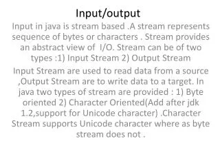
Chapter5:. Input/Output (I/O). Introduction (1). I/O refers to the communication between an information processing system (such as a computer) and outside world (a human). Inputs - signals or data received by the system. Outputs - signals or data sent from it.

E N D
Chapter5: Input/Output (I/O)
Introduction (1) • I/O refers to the communication between an information processing system (such as a computer) and outside world (a human). • Inputs - signals or data received by the system. • Outputs - signals or data sent from it. • I/O devices are used by a person (or other system) to communicate with a computer • Devices for communication between computers, such as modems and network, typically serve for both input and output.
Introduction (2) • In CA, combination of CPU and main memory (i.e. memory that the CPU can read and write to directly, with individual instructions) is considered the brain of a computer. • Any transfer of information from or to that combination, for example to or from a HDD, is considered I/O.
Introduction (3) • CPU and its supporting circuitry provide memory-mapped I/O that is used in low-level computer programming in the implementation of device drivers. • An I/O algorithm is one designed to exploit locality and perform efficiently when data reside on secondary storage, such as a disk drive.
Introduction (4) • I/O interface is required whenever I/O device is driven by CPU. Must be able to interpret the device address generated by the processor. • Handshaking should be implemented by interface using appropriate commands, and the processor can communicate with an I/O device through the interface.
Introduction (5) • If different data formats are being exchanged, the interface must be able to convert serial data to parallel form and vice-versa. There must be provision for generating interrupts and the corresponding type numbers for further processing by the processor if required. • A computer that uses memory-mapped I/O accesses hardware by reading and writing to specific memory locations, using the same assembly language instructions that computer would normally use to access memory.
I/O Problems • I/O – not mechanical connector but logic for performing a communication function • Wide variety of peripherals • Delivering different amounts of data • At different speeds • In different formats • All slower than CPU and RAM • Need I/O modules
Generic Model of I/O Module • Interface to CPU and Memory • Interface to one or more peripherals devices by tailored data links
External Devices • Classify into three categories: • Human readable • Screen, printer, keyboard • Machine readable • Monitoring and control • Communication • Modem • Network Interface Card (NIC)
External Device Block Diagram • i/face to I/O module in form of control, data, status signals • ctrl signals – determine function device to perform, accept data, report status • data – set of bit to be sent to/rec’d from I/O module • status signals – indicate state of device • ctrl logic – controls device’s operation in response to direction from I/O module • transducer – converts data from electric to other form
I/O Module Function • Control & Timing • To coordinate flow of traffic • CPU Communication • Command decoding, data, status reporting, address recognition • Device Communication • Involves command, status information, data • Data Buffering • Need for operating at high speed • Error Detection • Reporting error to processor
I/O Steps • CPU checks I/O module device status • I/O module returns status • If ready, CPU requests data transfer • I/O module gets data from device • I/O module transfers data to CPU • Variations for output, DMA, etc.
I/O Module Decisions • Hide or reveal device properties to CPU • Support multiple or single device • Control device functions or leave for CPU • Also O/S decisions • e.g. Unix treats everything it can as a file
I/O Techniques • Three principle techniques • Programmed I/O – direct & continuous control requesting operation • Interrupt-driven I/O – issues command to execute until operation interrupted • Direct Memory Access (DMA) – specialized I/O processor takes over control operation
1) Programmed I/O • CPU has direct control over I/O • Sensing status • Read/write commands • Transferring data • CPU waits for I/O module to complete operation • Wastes CPU time
Programmed I/O - detail • CPU requests I/O operation • I/O module performs operation • I/O module sets status bits • CPU checks status bits periodically • I/O module does not inform CPU directly • I/O module does not interrupt CPU • CPU may wait or come back later
I/O Commands • CPU issues address • Identifies module (& device if >1 per module) • CPU issues command • Control - telling module what to do • e.g. spin up disk • Test - check status • e.g. power? Error? • Read/Write • Module transfers data via buffer from/to device
Addressing I/O Devices • Under programmed I/O data transfer is very like memory access (CPU viewpoint) • Each device given unique identifier • CPU commands contain identifier (address)
I/O Mapping • Memory mapped I/O • Devices and memory share an address space • I/O looks just like memory read/write • No special commands for I/O • Large selection of memory access commands available • Isolated I/O • Separate address spaces • Need I/O or memory select lines • Special commands for I/O • Limited set
2) Interrupt Driven I/O • Overcomes CPU waiting • No repeated CPU checking of device • I/O module interrupts when ready
Interrupt Driven I/O Basic Operation • CPU issues read command • I/O module gets data from peripheral whilst CPU does other work • I/O module interrupts CPU • CPU requests data • I/O module transfers data
CPU Viewpoint • Issue read command • Do other work • Check for interrupt at end of each instruction cycle • If interrupted:- • Save context (registers) • Process interrupt • Fetch data & store
Design Issues • How do you identify the module issuing the interrupt? • How do you deal with multiple interrupts? • i.e. an interrupt handler being interrupted
Identifying Interrupting Module (1) • Different line for each module • PC • Limits number of devices • Software poll • CPU asks each module in turn • Slow
Identifying Interrupting Module (2) • Daisy Chain or Hardware poll • Interrupt Acknowledge sent down a chain • Module responsible places vector on bus • CPU uses vector to identify handler routine • Bus Master (vectored) • Module must claim the bus before it can raise interrupt • e.g. PCI & SCSI
Multiple Interrupts • Each interrupt line has a priority • Higher priority lines can interrupt lower priority lines • If bus mastering only current master can interrupt
Example - PC Bus • 80x86 has one interrupt line • 8086 based systems use one 8259A interrupt controller • 8259A has 8 interrupt lines
Sequence of Events • 8259A accepts interrupts • 8259A determines priority • 8259A signals 8086 (raises INTR line) • CPU Acknowledges • 8259A puts correct vector on data bus • CPU processes interrupt
ISA Bus Interrupt System • ISA bus chains two 8259As together • Link is via interrupt 2 • Gives 15 lines • 16 lines less one for link • IRQ 9 is used to re-route anything trying to use IRQ 2 • Backwards compatibility • Incorporated in chip set
3) Direct Memory Access (DMA) • Interrupt driven and programmed I/O require active CPU intervention • Transfer rate is limited • CPU is tied up • DMA is the answer
DMA Function • Additional Module (hardware) on bus • DMA controller takes over from CPU for I/O
DMA Operation • CPU tells DMA controller:- • Read/Write • Device address • Starting address of memory block for data • Amount of data to be transferred • CPU carries on with other work • DMA controller deals with transfer • DMA controller sends interrupt when finished
DMA Transfer Cycle Stealing • DMA controller takes over bus for a cycle • Transfer of one word of data • Not an interrupt • CPU does not switch context • CPU suspended just before it accesses bus • i.e. before an operand or data fetch or a data write • Slows down CPU but not as much as CPU doing transfer
Aside • What effect does caching memory have on DMA? • What about on board cache? • Hint: how much are the system buses available?
DMA Configurations (1) • Single Bus, Detached DMA controller • Each transfer uses bus twice • I/O to DMA then DMA to memory • CPU is suspended twice
DMA Configurations (2) • Single Bus, Integrated DMA controller • Controller may support >1 device • Each transfer uses bus once • DMA to memory • CPU is suspended once
DMA Configurations (3) • Separate I/O Bus • Bus supports all DMA enabled devices • Each transfer uses bus once • DMA to memory • CPU is suspended once
Intel 8237A DMA Controller • Interfaces to 80x86 family and DRAM • When DMA module needs buses it sends HOLD signal to processor • CPU responds HLDA (hold acknowledge) • DMA module can use buses
8237 DMA Usage of Systems Bus • E.g. transfer data from • memory to disk • Device requests service of DMA by pulling DREQ (DMA request) high • DMA puts high on HRQ (hold request), • CPU finishes present bus cycle (not necessarily present instruction) and puts high on HDLA (hold acknowledge). HOLD remains active for duration of DMA • DMA activates DACK (DMA acknowledge), telling device to start transfer • 5. DMA starts transfer by putting address of first byte on address bus and activating MEMR; it then activates IOW to write to peripheral. DMA decrements counter and increments address pointer. Repeat until count reaches zero • 6. DMA deactivates HRQ, giving bus back to CPU
Fly-By • While DMA using buses processor idle • Processor using bus, DMA idle • Known as fly-by DMA controller • Data does not pass through and is not stored in DMA chip • DMA only between I/O port and memory • Not between two I/O ports or two memory locations • Can do memory to memory via register • 8237 contains four DMA channels • Programmed independently • Any one active • Numbered 0, 1, 2, and 3