Download
1 / 33
340 likes | 569 Vues
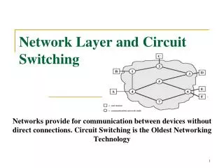
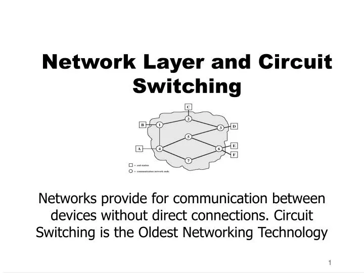
Network Layer and Circuit Switching. Networks provide for communication between devices without direct connections. Circuit Switching is the Oldest Networking Technology. Circuit-Switching.

E N D
Network Layer and Circuit Switching Networks provide for communication between devices without direct connections. Circuit Switching is the Oldest Networking Technology
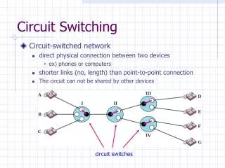
Circuit-Switching • Definition: Communication in which a dedicated communications path is established between two devices through one or more intermediate switching nodes • Oldest Networking Technology - more than a hundred years old • Dominant in both voice and data communications today • e.g. PSTN is a circuit-switched network • Relatively inefficient (100% dedication even without 100% utilization)
Circuit Switching • In circuit switching network any two stations wishing to communicate first establish a connection by requesting to the network. • The network responds by arranging a connection in such a way that a dedicated/physical path is established between the two parties • For the duration of the connection the path is dedicated to the connection and cannot be used for other connections • After the connection has been established the network becomes pretty much transparent to the two parties. Data can be exchanged transparently over the connection • After the parties are done communicating the connection is released by making a request to the network • The network responds by de-allocating the resources of the network that were dedicated to the connection
Circuit-Switching Stages • Circuit establishment • Transfer of information • point-to-point from endpoints to node • internal switching/multiplexing among nodes • Circuit disconnect
Circuit Switching Application • Circuit switching is well suited for analog voice communications as in the telephone network. • Circuit switching turns out to be rather in-efficient for data networks due to its resource allocation nature. • Circuit Switching is ill-suited to data communication because data traffic is BAD
Examples of Circuit Switching • Public Switched Telephone Network - PSTN • Private Automatic Branch Exchange - PABX • Integrated Services Digital Network - ISDN
Public Switched Telephone Network (PSTN) • PSTN is short for Public Switched Telephone Network, which refers to the international telephone system based on copper wires carrying analog voice data. This is in contrast to newer telephone networks base on digital technologies, such as ISDN and FDDI. • Telephone service carried by the PSTN is often called plain old telephone service (POTS).
POTS • POTS is short for plain old telephone service, which refers to the standard telephone service that most homes use. In contrast, telephone services based on high-speed, digital communications lines, such as ISDN and FDDI, are not POTS. • The main distinctions between POTS and non-POTS services are speed and bandwidth. POTS is generally restricted to about 33.6 kbps (33,600 bits per second) though several modem manufacturers have developed technologies that would enable rates of 56.6 kbps.
Subscribers Local loop Connects subscriber to local telco exchange Exchanges Telco switching centers Also known as end office >19,000 in US Trunks Connections between exchanges Carry multiple voice circuits using FDM or synchronous TDM Managed by IXCs (inter-exchange carriers) Public Switched Telephone Network (PSTN) Elements
About the Local Loop • The local loop is still predominantly twisted pair copper wire • Analog signaling is used on the local loop in PSTN • Digital signaling is used on the local loop in ISDN • Local loop is the bottleneck to high speed connectivity • Several technologies have been developed to give high speed data communication on the local loop
PABX • PBX = Private Branch Exchange • A Customer Premise Communication Switch used to connect customer telephones (and related equipment) to LEC central office lines (trunks), and to switch internal calls within the customer's telephone system. Modern PBXs offer numerous software-controlled features such as call forwarding and call pickup. A PBX uses technology similar to that used by a central office switch (on a smaller scale). (The acronym PBX originally stood for "Plug Board Exchange".)
ISDN • Abbreviation of integrated services digital network, an international communications standard for sending voice, video, and data over digital telephone lines. ISDN requires special metal wires and supports data transfer rates of 64 Kbps (64,000 bits per second). Most ISDN lines offered by telephone companies give you two lines at once, called B channels. You can use one line for voice and the other for data, or you can use both lines for data to give you data rates of 128 Kbps, four or five times the data rate provided by today's fastest modems.
B-ISDN • The original version of ISDN employs baseband transmission. Another version, called B-ISDN, uses broadband transmission and is able to support transmission rates of 1.5 million bits per second and higher. B-ISDN requires fiber optic cables and is not widely available.
Issues in Circuit Switched Networks • Routing • Control Signalling
Alternate Routing • Possible routes between two end offices are predefined • Originating switch selects the best route for each call • Routes listed in preference order • Different sets of routes may be used at different times • Routing paths can be fixed (1 route) or dynamic (multiple routes, selected based on current and historical traffic)
Adaptive Routing • Traffic reporting and analysis with new paths computed periodically, adapts to net load, events • Need to use algorithms to determine paths dynamically, based on load/congestion vectors
Control Signaling • Manage the establishment, maintenance, and termination of signal paths • Includes signaling from subscriber to network, and signals within network • In-channel Control Signalling • In-channel signaling uses the same channel for control signals and calls • Common Channel Control Signalling • Common-channel signaling uses independent channels for control (SS7)
Control Signaling Functions • Audible communication with subscriber • Transmission of dialed number • Call can not be completed indication • Call ended indication • Signal to ring phone • Billing info • Equipment and trunk status info • Diagnostic info • Control of specialist equipment
Location of Signaling • Subscriber to network • Depends on subscriber device and switch • DSS1 • Within network • Management of subscriber calls and network • More complex • SS7
Control Signal Sequence • Both phones on hook • Subscriber lifts receiver (off hook) • End office switch signaled • Switch responds with dial tone • Caller dials number • If target not busy, send ringer signal to target subscriber • Feedback to caller • Ringing tone, engaged tone, unobtainable • Target accepts call by lifting receiver • Switch terminates ringing signal and ringing tone • Switch establishes connection • Connection release when Source subscriber hangs up
Switch to Switch Signaling • Subscribers connected to different switches • Originating switch seizes interswitch trunk • Send off hook signal on trunk, requesting digit register at target switch (for address) • Terminating switch sends off hook followed by on hook (wink) to show register ready • Originating switch sends address
In Channel Signaling • Use same channel for signaling and call • Requires no additional transmission facilities • Inband • Uses same frequencies as voice signal • Can go anywhere a voice signal can • Impossible to set up a call on a faulty speech path • Out of band • Voice signals do not use full 4kHz bandwidth • Narrow signal band within 4kHz used for control • Can be sent whether or not voice signals are present • Need extra electronics • Slower signal rate (narrow bandwidth)
Drawbacks of In Channel Signaling • Limited transfer rate • Delay between entering address (dialing) and connection • Overcome by use of common channel signaling
Common Channel Signaling • Control signals carried over paths independent of voice channel • One control signal channel can carry signals for a number of subscriber channels • Common control channel for these subscriber lines • Associated Mode • Common channel closely tracks interswitch trunks • Disassociated Mode • Additional nodes (signal transfer points) • Effectively two separate networks
Signaling System Number 7 • SS7 • Common channel signaling scheme • Used in ISDN and inside PSTN • Optimized for 64k digital channel network • Call control, remote control, management and maintenance • Reliable means of transfer of info in sequence • Will operate over analog and below 64k • Point to point terrestrial and satellite links • Every element of the SS7 is replicated for resilience
SS7 Benefits • SS7 adds intelligence to a network • Basis of new end user services e.g. • 800 and 900 services • Mobile Telephone Service • Mobile subscriber authentication • Caller identification • Charging calls to a credit card • Charging calls to a calling card • SS7 standards include a standard client/server transaction protocol - Transaction Capabilities Application Part - TCAP
Blocking or Non-blocking • Blocking • A network is unable to connect stations because all paths are in use • A blocking network allows this • Used on voice systems • Short duration calls • Non-blocking • Permits all stations to connect (in pairs) at once • Used for some data connections