Download
1 / 125
1.27k likes | 1.5k Vues
Nitrogen Generating System. Operational Serviceable Degraded Temporary Serviceable Inoperative Unserviceable. NGS is fully operational. NGS is operational, but it is operating in a degraded condition. NGS is inoperative. No lights illuminated also indicates NGS is inoperative.

E N D
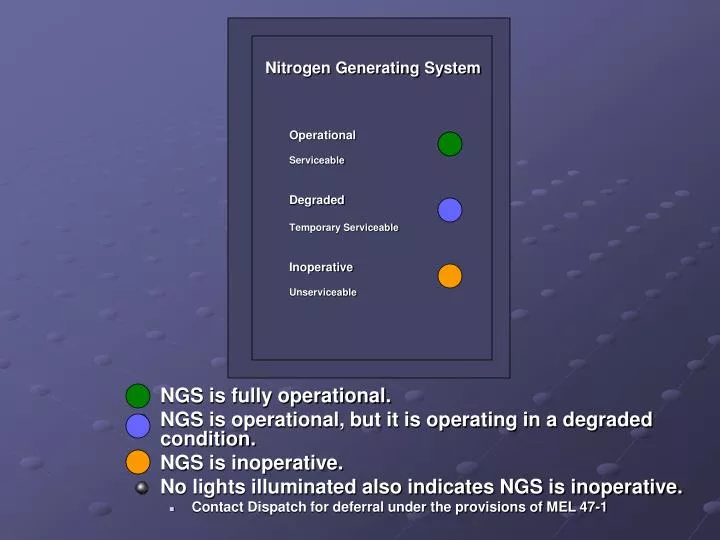
Nitrogen Generating System Operational Serviceable Degraded Temporary Serviceable Inoperative Unserviceable • NGS is fully operational. • NGS is operational, but it is operating in a degraded condition. • NGS is inoperative. • No lights illuminated also indicates NGS is inoperative. • Contact Dispatch for deferral under the provisions of MEL 47-1
GRD POWER AVAILABLE • Ground power is connected and meets aircraft power quality standards • (-300/500) Ground power is connected
MASTERCAUTION PUSH TO RESET ELEC BAT DISCHARGE • Normal indication for a battery start • The MASTER CAUTION light will not be illuminated • Battery switch must be on in order to apply ground power • Wait 5 seconds (60 seconds for an APU start) • There is no minimum battery voltage required to start the APU • Excessive battery discharge detected with the battery switch on • Item is not deferrable • A fully charged battery provides a minimum of 30 minutes of standby power, (N550WN and N551WN 60 minutes) • (N550WN and N551WN) a charging problem with either the main or auxiliary batteries
MASTERCAUTION PUSH TO RESET MASTERCAUTION PUSH TO RESET OVHT/DET • The indications for the FAULT/INOP test • A total of 5 lights FAULT APU DET INOP Fire Panel
FIRE WARN BELL CUTOUT MASTERCAUTION PUSH TO RESET MASTERCAUTION PUSH TO RESET FIRE WARN BELL CUTOUT OVHT/DET • The indications for the OVHT/FIRE test • AC power required for the wheel well light • A total of 11 lights DISCH DISCH WHEEL WELL DISCH A P U 1 2 ENG 1 OVERHEAT ENG 2 OVERHEAT Fire Panel
FIRE WARN BELL CUTOUT MASTERCAUTION PUSH TO RESET MASTERCAUTION PUSH TO RESET FIRE WARN BELL CUTOUT OVHT/DET • A or B fire loop inoperative for engine #1 • AC power required for wheel well light • (-300/-500): An illuminated FAULT light is the only indication that differs from a normal test • The exception is for an open circuit which will also cause the related ENGINE FIRE WARNING switch and ENGINE OVERHEAT light to remain extinguished WHEEL WELL DISCH DISCH DISCH FAULT A P U 1 2 ENG 1 OVERHEAT ENG 2 OVERHEAT or or Fire Panel ENG 1 OVERHEAT DISCH -300/500 1 -300/500
E T X E T S T 1 2 L R • EXT TEST switch is positioned to 1 or 2 and circuit continuity is normal APU
ALIGN • Steady-the related IRS is operating in the ALIGN mode, the initial ATT mode, or the shutdown cycle • Flashing-alignment cannot be completed due to IRS detection of: • Significant difference between previous and entered positions (unreasonable present position, i.e. SJC instead of SLC, LAS instead of LAX), or • No present position entry • Aircraft movement • Align light extinguished: • IRS not in ALIGN mode • With mode selector in NAV, alignment is complete, and all IRS information is available • With mode selector in ATT, attitude information is available • Heading information is available following entry of initial magnetic heading
MASTERCAUTION PUSH TO RESET FAULT IRS • Respective IRS system has detected a fault • A system fault affecting the related IRS ATT and/or NAV modes has been detected • The IRS ATT and/or NAV modes may be inoperative • IRS failure may be caused by loss of AC and DC power to the IRS; no warning lights will illuminate • Indication of a complete power loss: • Attitude flag on the respective ADI • A heading flag on the respective HSI • Loss of vertical speed information
MASTERCAUTION PUSH TO RESET DC FAIL IRS • Related IRS DC power has failed • DC power for the related IRS is not normal • If the other lights are extinguished, the IRS is operating normally on AC power • With both IRS DC FAIL lights illuminated, the switched hot battery bus is not powered, or the battery is nearly discharged • If the battery is discharged, fire protection capability from the Hot Battery Bus is lost
MASTERCAUTION PUSH TO RESET ON DC IRS • The related IRS is operating on DC power from the switched hot battery bus (AC power not normal) • If on the ground, the ground-call horn in the nose wheel well sounds, providing an alert that abattery drain condition exists (gate services-external power has failed) • Momentary illumination is normal during alignment self-test (OFF to NAV) • A timer removes DC power from the right IRS after 5 minutes
GPS • GPS failure • A failure in both GPS sensor units • A failure in a single GPS sensor unit when either system annunciator panel is pushed and held
MASTERCAUTION PUSH TO RESET PSEU OVERHEAD • A designated proximity switch electronic unit fault has been detected • If the light illuminates only during an annunciator recall, only a simple fault has been detected • The PSEU light monitors: • Takeoff configuration warnings • Landing configuration warnings • Landing gear • Air/ground sensing • Overwing exit doors • The PSEU light illuminates on the ground only • An actual failure is not deferrable • On ground—a fault is detected in the PSEU, or an overwing exit flight lock fails to disengage when commanded • In flight—inhibited from thrust lever advance for takeoff until 30 seconds after landing
MASTERCAUTION PUSH TO RESET ENG REVERSER • Fault detected in the related engine reverser system • If the REVERSER light illuminates inflight, additional system failures may cause deployment • Expect normal reverser operation after touchdown • If the REVERSER light illuminates on the ground, reverse thrust may not be available • Comparator senses a disagreement between the position of the isolation valve or thrust reverser control valve • (-300/500) Reverser isolation valve and the selector valve is not in commanded position • Disagreement between the reverser sleeve position sensors (one or more thrust reverser sleeves are not in commanded state) • Thrust lever commanded to stow and extinguishes 10 seconds later when the isolation valve closes (auto-restow circuit has been activated) • If this action does not occur within approximately 12 seconds, the MASTER CAUTION and ENG lights will illuminate • Failure has been detected in the synchronization shaft lock circuitry • (-300/500 N/A) • Takeoff or Landing is not authorized • Either thrust reverser is inoperative and the runway is contaminated with clutter or the braking action is less than “GOOD”
ON • Associated EEC is selected on • (-300/500) Associated PMC is selected on
MASTERCAUTION PUSH TO RESET ENG ON ALTN ALTN • The EEC has automatically selected the soft alternate mode • EGT limits must be observed in both normal and alternate control modes
MASTERCAUTION PUSH TO RESET ENGINE CONTROL ENG #1 or #2 • Engine control system fault • On the ground only with the engines operating, below 80 knots on the takeoff roll • Are inhibited for approximately 30 seconds after touchdown • Are not dispatchable due to faults in the engine control system
MASTERCAUTION PUSH TO RESET ENG INOP -300/500 • PMC inoperative when N2 is greater than 46% • PMC is selected off
MASTERCAUTION PUSH TO RESET ENG LOWIDLE • Thrust lever for either engine near idle and the MEC of either engine not commanded to maintain high idle RPM in-flight • Speed for either engine below 25% N1 in-flight • (-500) One or both start switches in FLT and one or both engines below 45% N1 above 500’ RA • RPM for one or both engines is below the minimum required for engine acceleration during a go-around • If an engine start lever is in CUTOFF, the light is deactivated -300/500
MASTERCAUTION PUSH TO RESET PASS OXY ON OVERHEAD • The system is activated: • Automatically by a pressure switch at a cabin altitude of 14,000 feet, or • When the passenger oxygen switch is positioned to ON • The masks have dropped
LEFTGEAR RIGHTGEAR • Related gear is down and locked • Landing gear warning horn is deactivated with all gear down and locked • Landing gear is down and locked as long as one green landing gear indicator light (center panel or overhead panel) for each gear is illuminated • There are no red indication lights for the aft overhead gear lights NOSEGEAR -700 ONLY, AFT OVERHEAD PANEL
MASTERCAUTION PUSH TO RESET OFF OVERHEAD • The flight recorder is not operating • Power failure • Loss of input data • Electronic malfunction • The test is invalid FLIGHT RECORDER
MASTERCAUTION PUSH TO RESET FLT CONT LOW PRESSURE • The flight control LOW PRESSURE light illuminated indicates the related hydraulic system pressure to ailerons, elevator and rudder is low • Flight control switch to standby rudder: • The standby hydraulic pump starts • Shuts off the related hydraulic system pressure to ailerons, elevators and rudder by closing the flight control shutoff valve • Opens standby rudder shutoff valve to pressurize standby rudder power control unit • The standby rudder power control on light illuminates (if installed) • The standby LOW PRESSURE light is armed • The flight control LOW PRESSURE light extinguishes (deactivated) when the standby rudder shutoff valve opens • Allows the standby system to power the rudder and thrust reversers A or B STBY RUD ON
MASTERCAUTION PUSH TO RESET FLT CONT LOW QUANTITY STANDBY • The standby hydraulic LOW QUANTITY light illuminated indicates low fluid level in the standby hydraulic reservoir (less than 50%) • Always armed • An actual standby system low quantity is not deferrable
MASTERCAUTION PUSH TO RESET FLT CONT LOW PRESSURE STANDBY • The standby hydraulic LOW PRESSURE light illuminated indicates low output pressure from the electric motor driven standby pump • Armed only when standby pump operation has been selected: • A or B flight control switch to standby rudder • Alternate flaps master switch to ALTERNATE FLAPS • Or automatic standby function is activated: • With a loss of system A or B • Flaps are extended • Airborne, or on the ground with a wheel speed greater than 60 knots • (RSEP, if installed) The main PCU force fight monitor (FFM) activates • An actual standby hydraulic pump failure is not deferrable
MASTERCAUTION PUSH TO RESET FLT CONT STBY RUD ON • The STBY RUD ON light illuminated indicates the standby rudder power control unit is pressurized (if installed) • This item may or may not be deferrable, for dispatching requirements, refer to MEL 27
MASTERCAUTION PUSH TO RESET FLT CONT YAW DAMPER • The YAW DAMPER light illuminated indicates the yaw damper is not engaged • Trips off: • B flight control switch to OFF or STBY RUD • Loss of external power (gate services)
MASTERCAUTION PUSH TO RESET FLT CONT FEEL DIFF PRESS • The FEEL DIFF PRESS light illuminated indicates the feel computer is sensing a significant pressure differential between hydraulic systems A and B or between the left and right elevator pitot pressure inputs • A leak in any portion of the system resulting in the illumination of the FEEL DIFF PRESS light is not deferrable
MASTERCAUTION PUSH TO RESET FLT CONT MACH TRIM FAIL • The MACH TRIM FAIL light illuminated indicates both channels of the Mach trim system have failed • If the light illuminates only when the system annunciator panel is pressed to recall, only a single channel has failed but the Mach trim system is still operative • Airspeed……………Limit To 280 Knots/.82 Mach Max (-300/500 .74 Mach Max)
MASTERCAUTION PUSH TO RESET FLT CONT SPEED TRIM FAIL • The SPEED TRIM FAIL light illuminated indicates both channels of the speed trim system have failed • If the light illuminates only when the system annunciator panel is pressed to recall, only a single channel has failed but the speed trim system is still operative.
MASTERCAUTION PUSH TO RESET FLT CONT AUTO SLAT FAIL • The AUTO SLAT FAIL light illuminated indicates both auto slat channels have failed • If the light illuminates only when the system annunciator panel is pressed to recall, only a single channel has failed but the auto slat system is still operative
ENG VALVE CLOSED FUEL VALVE CLOSED • Extinguished—related engine or spar fuel shutoff valve is open • Bright—related engine or spar fuel shutoff valve is in transit, or valve position and engine start lever or engine fire warning switch disagree • Dim—related engine or spar fuel shutoff valve (-300/500 fuel valve) is closed -300/500 SPAR VALVE CLOSED FUEL PANEL
MASTERCAUTION PUSH TO RESET FILTER BYPASS FUEL • The fuel FILTER BYPASS light illuminated indicates impending filter bypass due to contamination • Degraded engine operation may result due to a contaminated filter
VALVE OPEN • Bright—crossfeed valve is in transit, or valve position and crossfeed selector disagree • Dim—crossfeed valve is open • Extinguished—crossfeed valve is closed • The valve failed in the closed position is indicated by the crossfeed VALVE OPEN light illuminated bright with the crossfeed selector in the open position • The valve failed in the open position is indicated by the crossfeed VALVE OPEN light illuminated bright with the crossfeed selector in the closed position FUEL CROSSFEED VALVE
MASTERCAUTION PUSH TO RESET LOWPRESSURE FUEL CENTER TANK PUMP • Fuel pump output pressure is low and fuel pump switch is ON • With both center tank fuel pump switches ON: • Illumination of both LOW PRESSURE lights illuminate the MASTER CAUTION and FUEL system annunciator lights • Illumination of one LOW PRESSURE light illuminates the MASTER CAUTION and FUEL system annunciator lights only with MASTER CAUTION light recall • On newer aircraft, and those that have been modified, illumination of one LOW PRESSURE light illuminates the MASTER CAUTION and FUEL system annunciator lights without recall • With one center tank fuel pump switch OFF, illumination of opposite center tank LOW PRESSURE light illuminates the MASTER CAUTION and FUEL system annunciator lights • Extinguished—fuel pump output pressure is normal, or fuel pump switch is OFF • The lights may flicker when tank quantity is low and the aircraft is in turbulent air, climb, or descent
MASTERCAUTION PUSH TO RESET LOWPRESSURE FUEL MAIN TANK PUMP • Fuel pump output pressure is low and fuel pump switch is ON • Two LOW PRESSURE lights illuminated in the same tank illuminate the MASTER CAUTION and FUEL system annunciator lights • One LOW PRESSURE light causes the MASTER CAUTION and FUEL system annunciator lights to illuminate only on MASTER CAUTION light recall • Extinguished—fuel pump output pressure is normal • The lights may flicker when tank quantity is low and the aircraft is in turbulent air, climb, or descent
MASTERCAUTION PUSH TO RESET FAULT APU HIGH OIL TEMP • APU malfunction or high oil temperature within the APU • APU shuts down automatically • (-700) If the light is illuminated when APU switch is placed to OFF, light extinguishes in 5 minutes • If the fuel valve has failed, the FAULT light remains illuminated • Light is disarmed when the APU switch is in OFF position -300/500
MASTERCAUTION PUSH TO RESET MAINT APU LOW OIL QUANTITY • APU maintenance problem exists • APU may be operated • APU oil quantity insufficient for extended operation • Light is disarmed when APU switch is OFF -300/500
MASTERCAUTION PUSH TO RESET LOW OIL PRESSURE APU • APU low oil pressure • APU shuts down automatically • Normal indication during an APU start • If the light does not extinguish after the APU is running, an automatic shutdown will occur
MASTERCAUTION PUSH TO RESET OVER SPEED APU • APU RPM limit exceeded, the APU shuts down automatically • (-300/500) An APU start has been aborted prior to the APU reaching normal operating speed • The overspeed protection feature has failed a self-test during a normal APU shutdown • (-700) If light is illuminated when APU switch is placed to OFF, light extinguishes in 5 minutes • Light is disarmed when APU switch is in the OFF position
DISCH LOW OIL PRESSURE OVER SPEED FAULT A P U HIGH OIL TEMP • APU automatic shutdown protection: • APU fire • Low oil pressure • Fault (-300/500: High oil temperature) • Overspeed conditions • Other system faults monitored by the electronic control unit (ECU) (-300/500 N/A) • Fuel control unit failure • EGT exceedance -300/500
APU GENOFF BUS • APU is running but not powering a bus • (-300/500) APU is at its operating speed and not powering a generator bus
MASTERCAUTION PUSH TO RESET ELEC TRANSFER BUS OFF • The respective transfer bus is not powered • Item is not deferrable
MASTERCAUTION PUSH TO RESET ELEC SOURCE OFF • The related transfer bus is not powered by the last selected source • No source has been manually selected to power the related transfer bus • The manually selected source has been disconnected
MASTERCAUTION PUSH TO RESET ELEC BUS OFF -300/500 • The BUS OFF light illuminated indicates the respective generator bus is not powered
MASTERCAUTION PUSH TO RESET ELEC STANDBYPOWER OFF • One or more of the following busses are unpowered: • AC standby bus • DC standby bus • Battery bus • (-300/500): Standby busses are inactive • Item is not deferrable • Standby power switch to OFF: • AC standby bus • Static inverter, and • DC standby bus are not powered
MASTERCAUTION PUSH TO RESET ELEC DRIVE • Malfunction in the related generator drive unit • IDG failure • Engine shutdown • IDG automatic disconnect due to high oil temperature • IDG disconnected through the generator drive disconnect switch • It is deferrable • Southwest Airlines has now received MEL relief for an inoperative engine-driven generator (MEL 24-1) on aircraft N281 and subsequent • If an engine driven generator is inoperative, these aircraft may be dispatched at an altitude of FL220 or below (RBF #A-07-91) • The MEL/CDL block of the flight release will list MEL 24-1, and the REMARKS block will contain the altitude restriction of FL220 • If the APU generator is successfully placed on the bus, you may continue to the destination airport • (N281WN and subsequent) If the momentary underspeed when passing through FL260 causes an APU generator disconnect, simply wait for the APU to stabilize and then place the APU generator back on the bus
MASTERCAUTION PUSH TO RESET ELEC ELEC • A fault in the DC or standby power system • The light illuminates only on the ground • Item is not deferrable
MASTERCAUTION PUSH TO RESET ELEC TR UNIT • On the ground if any TR has failed • Inflight if TR 1 failed, or TR 2 and TR 3 failed • Item is not deferrable
GEN OFF BUS • IDG is not supplying power to the related transfer bus • (-300/500) Related generator is not supplying power to the related generator bus