Download
1 / 63
770 likes | 1.15k Vues
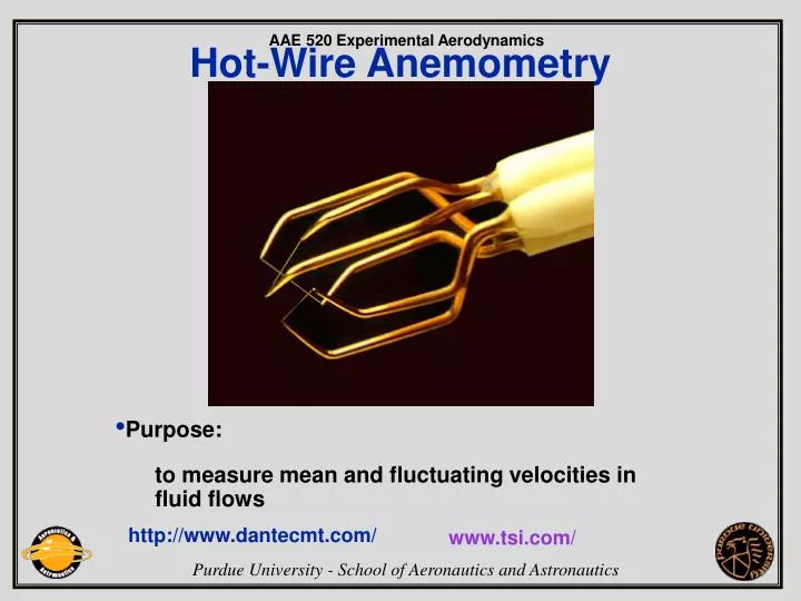
Hot-Wire Anemometry. Purpose: to measure mean and fluctuating velocities in fluid flows. http://www.dantecmt.com/. www.tsi.com/. Principles of operation. Consider a thin wire mounted to supports and exposed to a velocity U .

E N D
Hot-Wire Anemometry • Purpose: • to measure mean and fluctuating velocities in fluid flows http://www.dantecmt.com/ www.tsi.com/
Principles of operation • Consider a thin wire mounted to supports and exposed to a velocity U. When a current is passed through wire, heat is generated (I2Rw). In equilibrium, this must be balanced by heat loss (primarily convective) to the surroundings. • If velocity changes, convective heat transfer coefficient will change, wire temperature will change and eventually reach a new equilibrium.
Governing equation I • Governing Equation: E = thermal energy stored in wire E = CwTs Cw = heat capacity of wire W = power generated by Joule heating W = I2 Rw recall Rw = Rw(Tw) H = heat transferred to surroundings
Governing equation II Heattransferred to surroundings ( convection to fluid + conduction to supports + radiation to surroundings) Convection Qc = Nu · A · (Tw -Ta) Nu = h ·d/kf = f (Re, Pr, M, Gr,a ), Re = r U/m Conduction f(Tw , lw , kw, Tsupports) Radiation f(Tw4 - Tf4)
Simplified static analysis I • For equilibrium conditions the heat storage is zero: and the Joule heating W equals the convective heat transfer H • Assumptions • Radiation losses small • Conduction to wire supports small • Twuniform over length of sensor • Velocity impinges normally on wire, and is uniform over its entire length, and also small compared to sonic speed. • Fluid temperature and density constant
Simplified static analysis II Static heat transfer: W = H I2Rw = hA(Tw -Ta) I2Rw = Nukf/dA(Tw -Ta) h = film coefficient of heat transfer A = heat transfer area d = wire diameter kf = heat conductivity of fluid Nu = dimensionless heat transfer coefficient Forced convection regime, i.e. Re >Gr1/3 (0.02 in air) and Re<140 Nu = A1 + B1 · Ren = A2+ B2 · Un I2Rw2 = E2 = (Tw -Ta)(A + B · Un) “King’s law” The voltage drop is used as a measure of velocity.
Hot-wire static transfer function • Velocity sensitivity (King’s law coeff. A = 1.51, B = 0.811, n = 0.43) Output voltage as fct. of velocity Voltage derivative as fct. of velocity
Directional response I • Probe coordinate system Velocity vector U is decomposed into normal Ux, tangential Uy and binormal Uz components.
Directional response II • Finite wire (l/d~200) response includes yaw and pitch sensitivity: U2eff(a) = U2(cos2a + k2sin2a) q = 0 U2eff(q ) = U2(cos2q +h2sin2q ) a = 0 where: k, h = yaw and pitch factors a, q = angle between wire normal/wire-prong plane, respectively, and velocity vector • General response in 3D flows: U2eff = Ux2 + k2Uy2 + h2Uz2 Ueff is the effective cooling velocity sensed by the wire and deducted from the calibration expression, while U is the velocity component normal to the wire
Directional response III • Typical directional response for hot-wire probe (From DISA 1971)
Directional response IV • Yaw and pitch factors k1 and k2 (or k and h) depend on velocity and flow angle (From Joergensen 1971)
Probe types I • Miniature Wire Probes Platinum-plated tungsten, 5 mm diameter, 1.2 mm length • Gold-Plated Probes 3 mm total wire length, 1.25 mm active sensor copper ends, gold-plated Advantages: - accurately defined sensing length - reduced heat dissipation by the prongs - more uniform temperature distribution along wire - less probe interference to the flow field
Probe types II • For optimal frequency response, the probe should have as small a thermal inertia as possible. • Important considerations: • Wire length should be as short as possible (spatial resolution; want probe length << eddy size) • Aspect ratio (l/d) should be high (to minimise effects of end losses) • Wire should resist oxidation until high temperatures (want to operate wire at high T to get good sensitivity, high signal to noise ratio) • Temperature coefficient of resistance should be high (for high sensitivity, signal to noise ratio and frequency response) • Wires of less than 5 µm diameter cannot be drawn with reliable diameters
Probe types III • Film Probes Thin metal film (nickel) deposited on quartz body. Thin quartz layer protects metal film against corrosion, wear, physical damage, electrical action • Fiber-Film Probes “Hybrid” - film deposited on a thin wire-like quartz rod (fiber) “split fiber-film probes.”
Probe types IV • X-probes for 2D flows 2 sensors perpendicular to each other. Measures within ±45o. • Split-fiber probes for 2D flows 2 film sensors opposite each other on a quartz cylinder. Measures within ±90o. • Tri-axial probes for 3D flows 3 sensors in an orthogonal system. Measures within 70o cone.
Hints to select the right probe • Use wire probes whenever possible ü relatively inexpensive ü better frequency response ü can be repaired • Use film probes for rough environments ü more rugged ü worse frequency response ü cannot be repaired ü electrically insulated ü protected against mechanical and chemical action
Modes of anemometer operation Constant Current (CCA) Constant Temperature (CTA)
Constant current anemometer CCA • Principle: • Current through • sensor is kept • constant • Advantages: • - High frequency • response • Disadvantages: • - Difficult to use • - Output decreases with velocity • - Risk of probe burnout
Principle: Sensor resistance is kept constant by servo amplifier Advantages: - Easy to use - High frequency response - Low noise - Accepted standard Disadvantages: - More complex circuit Constant Temperature Anemometer CTA I
3-channel StreamLine with Tri-axial wire probe 55P91 Constant temperature anemometer CTA II
Wire resistance can be written as: Rw = Ro(1+a o(Tw-To)) Rw = wire hot resistance Ro = wire resistance at To a o = temp.coeff. of resistance Tw = wire temperature To = reference temperature Define: “OVERHEAT RATIO” as: a = (Rw-Ro)/Ro = a o(Tw-T0) Set “DECADE” overheat resistor as: RD = (1+a)Rw Modes of operation, CTA I
The voltage across wire is given by: E2 = I2Rw2 = Rw(Rw - Ra)(A1 + B1Un) or as Rw is kept constant by the servoloop: E2 = A + BUn Note following comments to CTA and to CCA: - Response is non-linear: - CCA output decreases - CTA output increases - Sensitivity decreases with increasing U Modes of operation, CTA II CTA output as fct. of U
Hot-wire Probes: For analysis of wire dynamic response, governing equation includes the term due to thermal energy storage within the wire: W = H + dE/dt The equation then becomes a differential equation: I2Rw = (Rw-Ra)(A+BUn) + Cw(dTw/dt) or expressing Tw in terms of Rw: I2Rw = (Rw-Ra)(A+BUn) + Cw/a oRo(dRw/dt) Cw = heat capacity of the wire ao= temperature coeff. of resistance of the wire Dynamic response, CCA I
Dynamic response, CCA II Hot-wire Probes: The first-order differential equation is characterised by a single time constant t : t = Cw/(aoRo(A+BU n) The normalised transfer function can be expressed as: Hwire(f) = 1/(1+jf/fcp) Where fcp is the frequency at which the amplitude damping is 3dB (50% amplitude reduction) and the phase lag is 45o. Frequency limit can be calculated from the time constant: fcp = 1/2pt
Dynamic response, CCA III • Hot-wire Probes: • Frequency response of film-probes is mainly determined by the thermal properties of the backing material (substrate). • The time constant for film-probes becomes: • t = (R/R0)2F2rsCsks/(A+BUn)2 • rs = substrate density • Cs = substrate heat capacity • ks = substrate heat conductivity • and the normalised transfer function becomes: • Hfilm(f) = 1/(1+(jf/fcp)0.5)
Dynamic characteristic may be described by the response to - Step change in velocity or - Sinusoidal velocity variation Dynamic response, CCA IV
Dynamic response, CCA V • The hot-wire response characteristic is specified by: For a 5 µm wire probe in CCA modet ~ 0.005s, typically. (Frequency response can be improved by compensation circuit) (From P.E. Nielsen and C.G. Rasmussen, 1966)
Dynamic response, CTA I • CTA keeps the wire at constant temperature, hence the effect of thermal inertia is greatly reduced: Time constant is reduced to t CTA = t CCA/(2aSRw) where a = overheat ratio S = amplifier gain Rw = wire hot resistance • Frequency limit: fc defined as -3dB amplitude damping (From Blackwelder 1981)
Dynamic response, CTA II • Typical frequency response of 5 mm wire probe (Amplitude damping and Phase lag): • Phase lag is reduced by frequency dependent gain (-1.2 dB/octave) (From Dantec MT)
Velocity calibration (Static cal.) • Despite extensive work, no universal expression to describe heat transfer from hot wires and films exist. • For all actual measurements, direct calibration of the anemometer is necessary.
Calibration in gases (example low turbulent free jet): Velocity is determined from isentropic expansion: Po/P = (1+(g -1)/2M 2)g /(g- -1) a0 = (g RT0 )0.5 a = ao/(1+(g -1)/2M 2)0.5 U = Ma Velocity calibration (Static cal.) II
Velocity calibration (Static cal.) III • Film probes in water • - Using a free jet of liquid issuing from the bottom of a container • - Towing the probe at a known velocity in still liquid • - Using a submerged jet
Typical calibration curve • Wire probe calibration with curve fit errors Curve fit (velocity U as function of output voltage E): U = C0 + C1E + C2E2 + C3E3 + C4E4 (Obtained with Dantec 90H01/02)Calibrator)
Dynamic calibration/tuning I • Direct method Need a flow in which sinusoidal velocity variations of known amplitude are superimposed on a constant mean velocity - Microwave simulation of turbulence (<500 Hz) - Sound field simulation of turbulence (>500 Hz) - Vibrating the probe in a laminar flow (<1000Hz) All methods are difficult and are restricted to low frequencies.
Dynamic calibration/tuning II • Indirect method, “SINUS TEST” Subject the sensor to an electric sine wave which simulates an instantaneous change in velocity and analyse the amplitude response. Typical Wire probe response Typical Fiber probe response
Dynamic calibration/tuning III • Indirect method “SQUARE WAVE TEST” Subject the sensor to an electric sine wave which simulates an instantaneous change in velocity and analyse the shape of the anemometer output (From Bruun 1995) For a wire probe (1-order probe response): Frequency limit (- 3dB damping): fc = 1/1.3 t
Dynamic calibration Conclusion: • Indirect methods are the only ones applicable in practice. • Sinus test necessary for determination of frequency limit for fiber and film probes. • Square wave test determines frequency limits for wire probes. Time taken by the anemometer to rebalance itself is used as a measure of its frequency response. • Square wave test is primarily used for checking dynamic stability of CTA at high velocities. • Indirect methods cannot simulate effect of thermal boundary layers around sensor (which reduces the frequency response).
Disturbing effects (problem sources) • Anemometer system makes use of heat transfer from the probe Qc = Nu · A · (Tw -Ta) Nu = h · d/kf = f (Re, Pr, M, Gr,a ), • Anything which changes this heat transfer (other than the flow variable being measured) is a “PROBLEM SOURCE!” • Unsystematic effects (contamination, air bubbles in water, probe vibrations, etc.) • Systematic effects (ambient temperature changes, solid wall proximity, eddy shedding from cylindrical sensors etc.)
Problem sourcesProbe contamination I • Most common sources: - dust particles - dirt - oil vapours - chemicals • Effects: - Change flow sensitivity of sensor (DC drift of calibration curve) - Reduce frequency response • Cure: - Clean the sensor - Recalibrate
Problem SourcesProbe contamination II • Drift due to particle contamination in air 5 mm Wire, 70 mm Fiber and 1.2 mm SteelClad Probes (From Jorgensen, 1977) Wire and fiber exposed to unfiltered air at 40 m/s in 40 hours Steel Clad probe exposed to outdoor conditions 3 months during winter conditions
Problem SourcesProbe contamination IV • Low Velocity - slight effect of dirt on heat transfer - heat transfer may even increase! - effect of increased surface vs. insulating effect • High Velocity - more contact with particles - bigger problem in laminar flow - turbulent flow has “cleaning effect” • Influence of dirt INCREASES as wire diameter DECREASES • Deposition of chemicals INCREASES as wire temperature INCREASES * FILTER THE FLOW, CLEAN SENSOR AND RECALIBRATE!
Problem SourcesProbe contamination III • Drift due to particle contamination in water Output voltage decreases with increasing dirt deposit (From Morrow and Kline 1971)
Problem SourcesBubbles in Liquids I • Drift due to bubbles in water In liquids, dissolved gases form bubbles on sensor, resulting in: - reduced heat transfer - downward calibration drift (From C.G.Rasmussen 1967)
Problem SourcesBubbles in Liquids II • Effect of bubbling on portion of typical calibration curve • Bubble size depends on - surface tension - overheat ratio - velocity • Precautions - Use low overheat! - Let liquid stand before use! - Don’t allow liquid to cascade in air! - Clean sensor! (From C.G.Rasmussen 1967)
Problem Sources (solved)Stability in Liquid Measurements • Fiber probe operated stable in water - De-ionised water (reduces algae growth) - Filtration (better than 2 mm) - Keeping water temperature constant (within 0.1oC) (From Bruun 1996)
Problem sourcesEddy shedding I • Eddy shedding from cylindrical sensors • Occurs at Re ~50 • Select small sensor diameters/ Low pass filter the signal (From Eckelmann 1975)
Problem SourcesEddy shedding II • Vibrations from prongs and probe supports: • - Probe prongs may vibrate due to eddy shedding from them or due induced vibrations from the surroundings via the probe support. • - Prongs have natural frequencies from 8 to 20 kHz • Always use stiff and rigid probe mounts.
Problem SourcesTemperature Variations I • Fluctuating fluid temperature • Heat transfer from the probe is proportional to the temperature difference between fluid and sensor. • E2 = (Tw-Ta)(A + B·Un) • As Tavaries: • - heat transfer changes • - fluid properties change • Air measurements: • - limited effect at high overheat ratio • - changes in fluid properties are small • Liquid measurements effected more, because of: • - lower overheats • - stronger effects of T change on fluid properties
Problem SourcesTemperature Variations II • Anemometer output depends on both velocity and temperature • When ambient temperature increases the velocity is measured too low, if not corrected for. (From Joergensen and Morot1998)
Problem SourcesTemperature Variations III Film probe calibrated at different temperatures