Download
1 / 22
230 likes | 541 Vues
Power Estimation & Analysis ; power calculation needs three models ; architecture, component, and activity. Architecture ; component allocation. Scheduling operations. clock & power network. Lower-level specification. Estimation vs. Analysis. Analysis ;

E N D
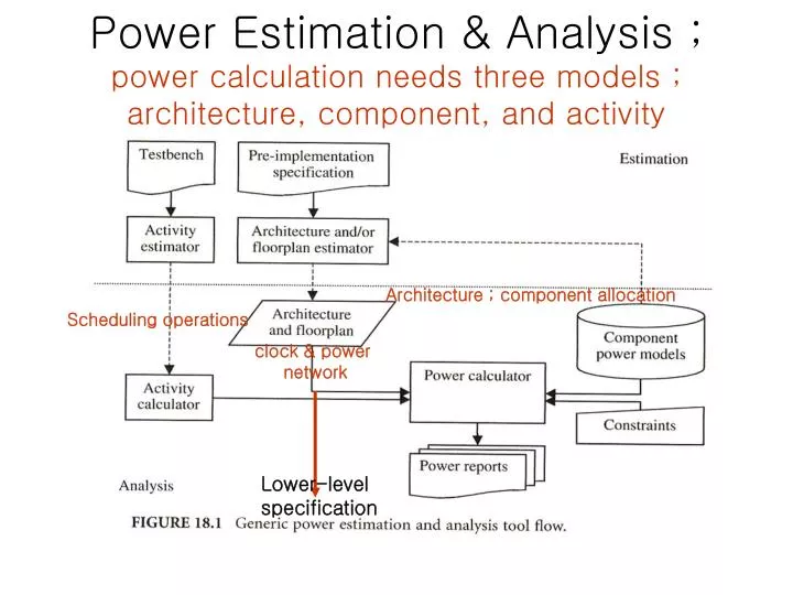
Power Estimation & Analysis ;power calculation needs three models ; architecture, component, and activity Architecture ; component allocation Scheduling operations clock & power network Lower-level specification
Estimation vs. Analysis • Analysis ; • for a given structure, i.e., netlist of components • Estimation (=design prediction followed by analysis) ; • when the information on the structure of the design is incomplete • Used to explore different design alternatives, and find the best • Example ; to estimate the interconnect power, one needs a floorplan prediction with clock and power network • In exploring the alternatives, often times, maintaining relative order between the prediction and actual implementation is enough.
Homework • Draw a Low-Power design flow based on • Top-down design flow starting from system-level to architecture, RTL, gate, circuit, and layout • Power analysis in each level using three models • Reference ; C. Piguet, Low-Power CMOS; circuit technology logic and CAD tools
System-level power analysis • System-level design Process ; • 1) allocation of components • 2) partitioning system’s task onto these components (or, sub-systems) • 3) organizing cooperation among components bound • System-level design Inputs ; • Specification ; • E.g., CDFG… • Environmental constraints ; • E.g., performance, power, cost, form factors, TTM, number/load of I/O’s • Design space restriction ; • E.g., enforced using some cores, available chip area, bus structure, etc.
Implementation model • Should be used when execution model is not available, typically using spread sheet • Usually start with a platform ; HW- and SW-platform • Basically three components ; • COTS (off-the-shelf components); • maybe only a single figure available from vendors such as watts/MHz@VDD for a processor • Guess based on experience, know-how • Customer-specific module; • Needs estimation based on prediction on number of gates, activity factor, and technology scaling factor • Power consumption of this module may be insignificant, but its use can replace the power-hungry processor. • Communication power; • Data transfer between blocks • Clock power, cross-coupling • What was ignored; software structure, data
Execution model • Typically given as a program in C, HDL, SystemC, or some heterogeneous combination of these • Allows more detailed power analysis as the dynamic system behavior is simulated ; • component power model, • system architecture, and • component activation pattern needed • For example, BFM (bus functional model) and the activity information for each processor components such as issue queue, branch prediction unit, execution unit, cache, register file are needed
Memory model • DTSE work by Catthor • Assume that memory is the dominant power consuming part in signal processing applications • Memory optimization in terms of power should be dome first • Objective; • increase data locality • Suppress memory access • Optimize memory hierarchy • By doing • Perform global loop and control flow transformations • Data reuse analysis • Storage cycle distribution • Memory allocation and assignment • In-place optimization
Memory model • Memory chip ; power model is available in the data sheet • Compiled memory core ; • Power model should be parameterized, at least, in terms of size. For that, simulation model is needed. But due to flat hierarchy simulation model of memory takes too long time. • Therefore, abstraction model is needed. Capacitance model is difficult to get as it reveals critical information of the memory vendor. -> Functional models not disclosing any internal cell structure is okay.
Other things to include in the execution model • Interconnect power model • Input ; physical layout and material properties • Built based on measurement and simulation • However, on-chip interconnect is difficult to model, especially when complex bus encoding is used. • Models for power management policy • Hardware for DPM (dynamic power mgmt) • Software • RTOS
Algorithm-Level Power Estimation in Orinoco • Activity estimation ; • Code instrumentation ; inserts protocol statements to capture the activity during execution • Architecture estimation ; • High-level synthesis ; • Scheduling • Allocation • Binding • Physical Planning • Floorplanning • Clock tree generation
Algorithmic-level power estimation and analysis • Algorithmic-level design • Objective; optimize in terms of performance, cost and power • Means; • Selection of algorithm performing the requested function • Optimization of the algorithm • Partitioning the algorithm into HW and SW
Algorithm selection ; selecting the most power-efficient one • Comparison is based on the most power-efficient realization without actual implementation. • Optimization ; • Reducing # of control statements, e.g., by loop unrolling, local statement reordering, memory access reordering • Floating-point for SW vs. fixed-point arithmetic for HW • Partitioning ; • Trade-off analysis between HW and SW implementations • SW-to-HW transformation ; moving the computational kernels of the algorithm to power-optimized application-specific hardware • No need for consecutive control steps to perform a single instruction • No need for memory access to find out what to do next • Minimal datapath just for performing the given task • Maximal concurrency exploitable compared to processor core
Software power analysis • Objective ; • Compare different programs • Select processors • Optimize software • Three level of granularity • Source code level • Instruction level • BFM level • Execution performed on • Target processor • Another processor • Simulator
RTL Power Modeling = Constructing a model P=P (X1,X2,…Xn) from n model parameters • Model granularity ; • not too big • Not too small • FSMD (FSM with datapath) is a reasonable choice • Model Parameters ; • What parameters are to be included in the model? • Model parameters must be observable at the RTL • P total = k AiCi ; Power model decoupled into two separate models, i.e., activity model and capacitance model
Dual bit type for representing fixed-point data • Capacitance for each bit position in the register experiences a different history • Instead of white noise assumption for each bit position, assume a proper correlation (with ) between consecutive data in the same bi tposition