Download
1 / 7
70 likes | 161 Vues
MONALISA Compact Straightness Monitor (CSM) simulation and Calibration. Summer Project 2008. Compact Straightness Monitor. 6D position transferred from left to right Integral use of sturdy endplates required. Preliminary simulation results of CSM Resolution: s y :10nm

E N D
MONALISACompact Straightness Monitor (CSM) simulationand Calibration Summer Project 2008
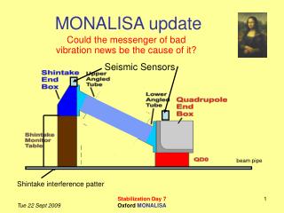
Compact Straightness Monitor • 6D position transferred from left to right • Integral use of sturdy endplates required. • Preliminary simulation results of CSM Resolution: • sy:10nm • distance meter resolution: 1nm = Resolution in z-direction • Positional change of optics components with respect to each other: 1nm. That’s the challenge! • Assuming launch and Retro-Reflector form perfect points 10cm
Compact Straightness Monitor • 6D position transferred from left to right • Integral use of sturdy endplates required. • Preliminary simulation results of CSM Resolution: • sy:10nm • distance meter resolution: 1nm = Resolution in z-direction • Positional change of optics components with respect to each other: 1nm. That’s the challenge! • Assuming launch and Retro-Reflector form perfect points 10cm
Titanium Compact Straightness Monitor Calibration Constants • Launch not from single point: • We don’t exactly know where this point is • We don’t know the relative position of the two launch heads that form a pair with respect to each other • We don’t know the relative position of the four launch pairs with respect to each other.
10cm Calibration • Make mathematical model for perfect system • Implement Model in Matlab • Graphical representation • Solve system • System with 3 points can be solved analytically • Needs minimization since measurements are not perfect: Method of Least Squares. • Next one could include errors on distance measurements • Finally lets assume we do not know the relative position of the 4 origin circles with respect ot each other. Calibration Method: • Move target around (on motion stage) where one knows exact position of target motion • Implement this in mathematical model and solve for position of 4 circles This is hard to start That is better/easier
Calibration • Make mathematical model for perfect system • Implement Model in Matlab • Graphical representation • Solve system • System with 3 points can be solved analytically • Needs minimization since measurements are not perfect: Method of Least Squares. • Next one could include errors on distance measurements • Finally lets assume we do not know the relative position of the 4 origin circles with respect ot each other. Calibration Method: • Move target around (on motion stage) where one knows exact position of target motion • Implement this in mathematical model and solve for position of 4 circles This is hard to start That is better/easier
Calibration • Make mathematical model for perfect system • Implement Model in Matlab • Graphical representation • Solve system • System with 3 points can be solved analytically • Needs minimization since measurements are not perfect: Method of Least Squares. • Next one could include errors on distance measurements • Finally lets assume we do not know the relative position of the 4 origin circles with respect ot each other. Calibration Method: • Move target around (on motion stage) where one knows exact position of target motion • Implement this in mathematical model and solve for position of 4 circles • Now one needs to do the same thing in 3D for the real system • Move one platform with respect to the other • Links to Least Square description and procedures used to calibrate LiCAS can be found on web page. 10cm