Download

1 / 66
800 likes | 1.04k Vues
Industrial Microbiology INDM 4005 Lecture 13 22/03/04. The stirred tank bioreactor.

E N D
Industrial Microbiology INDM 4005 Lecture 13 22/03/04
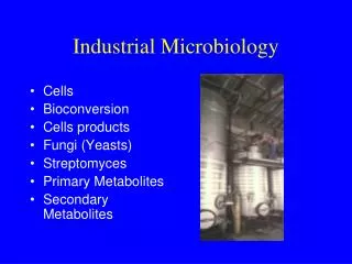
The stirred tank bioreactor 1. Introduction2. Standard geometry of a stirred tank bioreactor3. Headspace volume4. Basic features of a stirred tank bioreactor4.1. Agitation system4.1.1 Top entry and bottom entry impellers4.1.2 Mechanical seals4.2 Oxygen delivery system4.2.1 Compressor4.2.2 Air sterilization system4.2.3 Positive pressure4.2.4 Sparger4.2.5 Effect of impeller speed4.2.6 Air flow rate
The stirred tank bioreactor 4.3 Foam control4.4 Temperature control system4.5 pH control system4.5.1 Neutralizing agents4.5.2 Setpoint and deadband4.6 Cleaning and sterilization facilities5. Agitator design and operation5.1 Radial flow impellers5.1.1 Rushton turbine5.2 Axial flow impellers5.3 Intermig impeller
1. Introduction A typical bioreactor used for microbial fermentations is shown in the following figure: Laboratory scale bioreactors with liquid volumes of less than 10 litres are constructed out of Pyrex glass. For larger reactors,stainless steel is used.
2. Standard geometry of a stirred tank bioreactor • A stirred tank reactor will either be approximately cylindrical or have a curved base. A curved base assists in the mixing of the reactor contents. • Stirred tank bioreactors are generally constructed to standard dimensions. • That is, they are constructed according to recognised standards such as those published by the International Standards Organisation and the British Standards Institution. • These dimensions take into account both mixing effectiveness and structural considerations.
Standard geometry of a stirred tank bioreactor • A mechanically stirred tank bioreactor fitted with • a sparger and • a rushton turbine • will typically have the following relative dimensions:
3. Headspace volume • A bioreactor is divided in a working volume and a head-space volume. • The working volume is the fraction of the total volume taken up by the medium, microbes, and gas bubbles. • The remaining volume is called the headspace. • Typically, the working volume will be 70-80% of the total fermenter volume. • This value will however depend on the rate of foam formation during the reactor. If the medium or the fermentation has a tendency to foam, then a larger headspace and smaller working volume will need to be used.
4. Basic features of a stirred tank bioreactor • A modern mechanically agitated bioreactor will contain:
Basic features * An agitator system * An oxygen delivery system *A foam control system * A temperature control system * A pH control system * Sampling ports * A cleaning and sterilization system. * A sump and dump line for emptying of the reactor
4.1 Basic features of a stirred tank bioreactor - Agitation system • The function of the agitation system is to • provide good mixing and thus increase mass transfer rates through the bulk liquid and bubble boundary layers. • provide the appropriate shear conditions required for the breaking up of bubbles. • The agitation system consists of the agitator and the baffles. • The baffles are used to break the liquid flow to increase turbulence and mixing efficiency. The role of the baffles is discussed in depth in a later section. • The agitator consists of the components shown in the following diagram:
Agitation system • The agitator consists of the components shown in the following diagram:
Agitation system • The number of impellers will depend on the height of the liquid in the reactor. Each impeller will have between 2 and 6 blades. Most microbial fermentations use a Rushton turbine impeller. • A single phase (ie. 240 V) agitator drive motor can be used with small reactors. However for large reactors, a 3 phase motor (ie 430 V) should be used. The latter will tend to require less current and therefore generate less heat. • Speed control or speed reduction devices are used to control the agitation speed.
4.1.1 Basic features of a stirred tank bioreactor; Agitation system - Top entry and bottom entry impellers • The impeller shaft can enter from the bottom of the tank or from the top. A top entry impeller ("overhung shaft") is more expensive to install as the motor and the shaft will need to be structurally supported:
Bottom entry impellers • A reactor with bottom entry impeller however will need higher maintenance due to damage of the seal by particulates in the medium and by medium components that crystallize in the seal when reactor is not in use: • Bottom entry agitators tend to require more maintenance than top entry impellers due to the formation of crystals and other solids in the seals
4.1.2 Basic features of a STRAgitation system - Mechanical seals • The mechanical seal is used prevent contaminants from entering the reactor and to prevent organisms from escaping through the shaft. • The seal uses vapours from the liquid for lubrication. • It is therefore important that you do not turn the shaft when the tank is dry so as not to damage the seal.
4.2 Basic features of a stirred tank bioreactor - Oxygen delivery system. • The oxygen delivery system consists of • a compressor • inlet air sterilization system • an air sparger exit air sterilization system
4.2.1 Basic features of a stirred tank bioreactor; Oxygen delivery system - Compressor
Oxygen delivery system - Compressor • A compressor forces the air into the reactor. The compressor will need to generate sufficient pressure to force the air through the filter, sparger holes and into the liquid. • Air compressors used for large scale bioreactors typically produce air at 250 kPa. The air should be dry and oil free so as to not block the inlet air filter or contaminate the medium. • Note that it is very important that an "instrument air" compressor is not used. Instrument air is typically generated at higher pressures but is aspirated with oil. Instrument air compressors are used for pneumatic control
4.2.2 Basic features of a stirred tank bioreactor; Oxygen delivery system - Air sterilization system • Sterilization of the inlet air is undertaken to prevent contaminating organisms from entering the reactor. • The exit air on the other hand is sterilized not only to keep contaminants from entering but also to prevent organisms in the reactor from contaminating the air. • A common method of sterilising the inlet and exit air is filtration. For small reactors (with volumes less than 5 litres), disk shaped hydrophobic Teflon membranes housed in a polypropylene housing is used. are used. Teflon is tough, reusable and does not readily block.
Sterilisation of the air For larger laboratory scale fermenters (up to 1000 litres), pleated membrane filters housed in polypropylene cartridges are used.
Sterilisation of the air • By pleating the membrane, it is possible to create a compact filter with a very large surface area for air filtration. Increasing the filtration area decreases the pressure required to pass a given volume of air through the filter. • Sterilization of the inlet and exit air in large bioreactors (> 10,000 litres) can present a major design problem. Large scale membrane filtration is a very expensive process. The filters are expensive as they are difficult to make and the energy required to pass air through a filter can be quite considerable. • Heat sterilization is alternative option. Steam can be used to sterilize the air. With older style compressors, it was possible to use the heat generated by the air compression process to sterilize the air. However, compressors are now multi-stage devices which are cooled at each stage and disinfecting temperatures are never reached.
Condenser In small reactors, the exit air system will typically include a condenser.
Condenser • The condenser is a simple heat exchanger through which cool water is passed. • Volatile materials and water vapour condense on the inner condenser surface. • This minimizes water evaporation and the loss of volatiles. • Drying the air also prevents blocking of the exit air filter with water
4.2.3 Basic features of a STROxygen delivery systemAir sterilisation system - Positive pressure • During sterilisation the concept of "maintaining positive pressure" will often be used. • Maintaining positive pressure means that during sterilisation, cooling and filling and if appropriate, the fermentation process, air must be pumped into the reactor. • In this way the reactor is always pressurised and thus aerial contaminants will not be "sucked" into the reactor. • It is very important that positive pressure is maintained when the bioreactor is cooled following sterilisation. Without air being continuously pumped into the reactor, a vacuum will form and contaminants will tend to be drawn into the reactor.
Air sterilisation system - Positive pressure Maintaining positive pressure at all stages of the fermentation setup and operation is an important aspect of reducing the risk of contamination With aeration, positive pressure is always maintained and contaminants are pushed away from the reactor Without aeration, a vacuum forms as the reactor cools.
4.2.4 Basic features of a stirred tank bioreactor Oxygen delivery system - Sparger • The air sparger is used to break the incoming air into small bubbles. • Although various designs can be used such as porous materials made of glass or metal, the most common type of filter used in modern bioreactors is the sparge ring:
Oxygen delivery system - Sparger • A sparge ring consists of a hollow tube in which small holes have been drilled. A sparge ring is easier to clean than porous materials and is less likely to block during a fermentation. • The sparge ring must located below the agitator and will have approximately the same diameter as the impeller. • Thus, the bubbles rise directly into the impeller blades, facilitating bubble break up.
Oxygen delivery system - Sparger During the emptying of a fermenter, it is important that the air feed valve is closed. This will minimize the contamination of the inlet air line
4.2.5 Basic features of a STR Oxygen delivery system - Effect of impeller speed • As discussed in another lecture, the shear forces that an impeller generates play a major role in determining bubble size. If the impeller speed is to slow then the bubbles will not be broken down. In addition, if the impeller speed is too slow, then the bubbles will tend to rise directly to the surface due to their buoyancy. Fast impeller speed Slow impeller speed Smaller bubbles will be generated and these bubbles will move with throughout the reactor increasing the gas hold up and bubble residence time The bubbles will not be sheared into smaller bubbles and will tend to rise directly towards the surface
Oxygen delivery system - Effect of impeller speed • Another consequence of too slow an impeller speed is a flooded impeller. • Under these conditions, the bubbles will accumulate and coalesce under the impeller, leading to the formation of large bubbles and poor oxygen transfer rates. • A similar phenomenon will happen when aeration rate is too high. • In this case, the oxygen transfer efficiency will be low
4.2.6 Basic features of a STROxygen delivery system - Air flow rates • Air flow rates are typically reported in terms of • volume per volume per minute or vvm which is defined as:
Air flow rates Note the unit convention. The air flow rate and liquid volume must have the same basal unit. The air flow rate must be expressed in terms of volume per minute
4.3 Basic features of a STR - foam control system • Foam control is an essential element of the operation of a sparged bioreactor. The following photograph shows the accumulation of foam in a 2 litre laboratory reactor.
Foam control system • Excessive foam formation can lead to blocked air exit filters and to pressure build up in the reactor. • The latter can lead to a loss of medium, damage to the reactor and even injury to operating personnel. • Foam is typically controlled with aid of antifoaming agents based on silicone or on vegetable oils. • Excessive antifoam addition can however result in poor oxygen transfer rates.
The antifoam requirement will depend on • the nature of the medium. Media rich in proteins will tend to foam more readily than simple media. • the products produced by the fermentation. Secreted proteins or nucleic acids released as a result of cell death and hydrolysis have detergent like properties. • the aeration rate and stirrer speed. Increasing the aeration rate and stirrer speed increases foaming problems. • the use of mechanical foam control devices Foam control devices such as mechanical and ultrasonic foam breakers help to reduce the antifoam requirement. • The head space volume The larger headspace volume, then the greater the tendency for the foam to collapse under its own weight. For example, for fermentations in which high levels of foam is produced, a 50% headspace volume may be required. • Condenser temperature In laboratory scale reactors, a cold condenser temperature can help to control the foam. The density of the foam increases when it moves from the warm headspace volume to the cold condenser region. This causes the foam to collapse.
Foam is typically detected using two conductivity or "level" probes. When the upper level probe is above the foam level, no current will pass between the level probes and the antifoam pump remains turned off. When the upper level probe is immersed in the foam layer, a current is carried in the foam. This causes the antifoam to turn on.
Foam control system • One probe is immersed in the fermentation liquid while the other placed above the liquid level. • When the foam reaches the upper upper probe, a current is carried through the foam. • The detection of a current by the foam controller results in the activation of a pump and the antifoam is then added until the foam subsides.
4.4 Basic features of a stirred tank bioreactor - Temperature control system • The temperature control system consists of • temperature probes • heat transfer system • Typically the heat transfer system will use a "jacket" to transfer heat in or out of the reactor. The jacket is a shell which surrounds part of the reactor. The liquid in the jacket does not come in direct contact with the fermentation fluid.
Temperature control system • The jacket will typically be "dimpled" to encourage turbulence in the jacket and thus increase the heat transfer efficiency. • An alternative to using jackets are coils. Coils have a much higher heat transfer efficiency than jackets. However coils take up valuable reactor volume and can be difficult to clean and sterilize.
Temperature control system • The heating/cooling requirements are provided by the following methods: • Laboratory scale reactors Pilot and production scale reactors • HeatingElectric heaters Steam generated in boilers • requirements • CoolingTap water or Cooling water produced by • requirementsrefrigerated water baths cooling towers or refrigerants • such as ammonia.
Temperature control system • In pilot and production scale reactors, heating is typically only required during the initial stages and final stages of the fermentation as most processes which occur during a fermentation process, including • the biological reactions (eg. growth) • chemical reactions • mixing • are exothermic.
4.5 Basic features of a stirred tank bioreactor - pH control system • The pH control system consists of • a pH probe • alkali delivery system • acid delivery system The pH probe is typically steam sterilizable
4.5.1 Basic features of a stirred tank bioreactor pH control system - Neutralizing agents • The neutralizing agents used to control pH should be non-corrosive. They should also be non-toxic to cells when diluted in the medium. • Potassium hydroxide is preferred to NaOH, as potassium ions tend to be less toxic to cells than sodium ions. However KOH is more expensive than NaOH. Sodium carbonate is also commonly used in small scale bioreactor systems. • Hydrochloric acid should never be used as it is corrosive even to stainless steel. • Likewise sulphuric acid concentrations should not be between 10% and 80% as between this range, sulphuric acid is most corrosive.
Neutralizing agents • For fermentations that produce large amounts of acids, for example lactic acids fermentation using media containing high sugar concentrations, high concentrations of alkali (4 M and above) are preferred. This will prevent dilution of the medium due to the addition of excessive addition of the alkali solution. • For laboratory fermenters, a peristaltic pump is used to add the pH adjusting agents. Silicone tubing is often used. However, note that silicone tubing will decay in the presence of high alkali concentrations. Thick walled slicone tubing should be used. • Alternatively Tygon or Neoprene tubing can be used. Tygon is not autoclavable but can be sterilized by passing the NaOH through the tubing for about 1 hour. Neoprene is autoclavable but is not transparent or translucent as is Tygon or silicone.
4.5.2. Basic features of a stirred tank bioreactor pH control system - Setpoint and deadband
Setpoint and deadband • The pH control system (and indeed all other fermenter control systems) are designed to have a deadband. A deadband is used to prevent excessive alkali and acid addition. • The pH control deadband is shown in the following diagram:
Setpoint and deadband • The setpoint is the pH at which the fermenter is being attempted to be controlled at. For example, if the fermentation is to be run at a constant pH of 6.5, then the setpoint is set to 6.50. • If for example, a 5% deadband is used, then the upper deadband limit will be • 1.05 x 6.5 = 6.83 • and the lower deadband limit will be • 0.95 x 6.5 = 6.18 • If the deadband is too small, then it is possible that pH will often overshoot and undershoot the deadbands leading to excessive alkali and acid addition. The trade off is that a wide deadband will lead to less precise pH control. • As many fermentations tend to produce acids rather than substances that increase the pH, acid addition is often not required. Indeed not all fermentations need continuous pH control.
4.6. Basic features of a stirred tank bioreactor - Cleaning and sterilization facilities. • Small scale reactors are taken apart and then cleaned before being re-assembled, filled and then sterilized in an autoclave. • However, reactors with volumes greater than 5 litres cannot be placed in an autoclave and sterilized. These reactors must be cleaned and sterilized "in place". This process is referred to "Clean in Place”. • CIP involves the complete cleaning of not only the fermenter but also all lines linked to the internal components of the reactor. Steam, cleaning and sterilizing chemicals, spray balls and high pressure pumps are used in these processes. The process is usually automated to minimize the possibility of human error.