Download
1 / 32
330 likes | 507 Vues
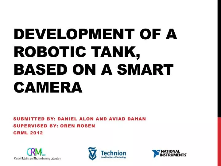
Development of a Robotic Tank, Based on a Smart Camera. Submitted by: Daniel Alon and Aviad Dahan Supervised by: Oren Rosen CRML 2012. Table of contents. Background Stages of the Project - Training & Preparations - Design & Architecture - Generating PWM Signal

E N D
Development of a Robotic Tank, Based on a Smart Camera Submitted by: Daniel Alon and AviadDahan Supervised by: Oren Rosen CRML 2012
Table of contents • Background • Stages of the Project • - Training & Preparations • - Design & Architecture • - Generating PWM Signal • - Implementation of a Close-loop movement • - Video Display & Processing • - Semi-Autonomous movement & tracking • Future Development • Summary • Live Demonstration
Background - Our Inspiration The Mars Rover:
Background - Our Goal Developing a Robotic Tank based on National Instruments Hardware and Software with Semi-Autonomous abilities.
Background – The Innovation • Image Processing – utilizing a NI smart camera • Control – first smartphone controlled project in the EE faculty • State of the art technology
Training & Preparations • Thoroughly investigating LabVIEW, which is the Project’s development environment. • Learning the FPGA, Real Time, and Robotics Modules of LabVIEW. • Studying the image processing module of National Instruments – NI Vision assistant.
Design & Architecture -The robotic tank Traxter II by Robotics Connection:
Design & Architecture-The Controller National Instruments SB-RIO 9631:
Design & Architecture -The Controller Controller Attributes: • 266 MHz processor, 128 MB nonvolatile storage, 64 MB DRAM for deterministic control and analysis. • Integrated 1M gate reconfigurable I/O (RIO) FPGA for custom timing, inline processing, and control. • 110 3.3 V (TTL/5 V tolerant) DIO lines, 32 16-bit analog inputs, four 16-bit analog outputs.
Design & Architecture -The Controller Controller Attributes: • 10/100BASE-T Ethernet port and RS232 serial port, 19 to 30 VDC supply input. • Easily embedded in high-volume applications that require flexibility, reliability, and high performance. • Ideal for low- to medium-volume applications and rapid prototyping.
Design & Architecture -The camera NI 1742 Smart-Camera:
Design & Architecture -The Camera Camera Attributes: • Monochrome 640 x 480 SONY CCD image sensor. • 533 MHz PowerPC processor. • Video capturing at up to 60 frames per second. • Quadrature encoder support, optoisolated digital I/O, and dual Gigabit Ethernet.
Design & Architecture -The Camera Camera Attributes: • Program with LabVIEW Real-Time Module or configure with Vision Assistant. • Highly compatible with Vision Assistant • Easy to use stand-alone, real time programming environment for vision applications.
Design & Architecture - Communication • Done By a Wireless router. • Each component has a static IP.
Design & Architecture -Power supplies Three 11.1 Volt Li-Po Batteries which located in the compartment cabin underneath the robot. Power requirements :
Design & Architecture Ethernet Wi-Fi router console controller Encoders Encoders PWM Wi-Fi driver driver Ethernet Smartphone camera Motor R Motor L Final Block Diagram of the Solution:
Design & Architecture The Result:
Generating PWM Signal • In order to control the motors, a PWM signal is being generated. • PWM is described as followed: • A square wave with a fixed cycle time and amplitude is being set. • The duty cycle of the wave is proportional to the power that we want to deliver to the motors.
Implementation of a Closed-Loop Movement • Android based Smartphone sends gyrometer and accelerometers signals to the SB-RIO controller, via Wi-Fi. • The messaging protocol between the smartphone and the SB-RIO controller is OSC. • The data from the smartphone is being processed in the controller and being translated into a PWM signal. • The motors are responding according to the PWM signal.
Video Display & Processing • Our target is a black circle. based on the robot’s pose, the circle may be interpreted as an ellipse. • Using the NI Vision Assistant, a Real Time ellipse detection algorithm was written. • The image processing algorithm is implemented on the camera. • The output is shown on the console’s monitor via LabVIEW VI.
Semi autonomous movement & tracking Scan Lock Act The algorithm:
Future developments & possible uses • Sequel project in CRML – An autonomous, smartphone controlled robot for indoor mapping. • Power consumption • All-Terrain mobilty • Military uses. • Research uses.
Summary • Multidisciplinary • First smartphone & hardware project in EE faculty • Ease of implementation • State of the art technology • Wrapping up
Appreciations & Thanks Oren Rosen – Supervisor. Kobi Kohai – CRML Lab Engineer. OrlyWigderson - CRML Lab Practical Engineer. EranCastiel - National Instruments Israel.