Download
1 / 13
200 likes | 1.51k Vues
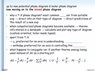
Cause and Effect Diagram ( C&E, Ishikawa, Fault or Fishbone Diagram ). Objective. In This Module We Will…. Define a Cause and Effect diagram Understand the elements of C&E analysis Understand why and when to use C&E diagrams Understand the importance of team involvement when brainstorming

E N D
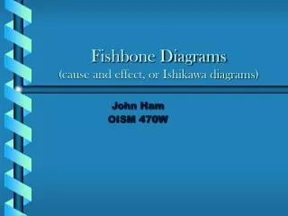
Cause and Effect Diagram(C&E, Ishikawa, Fault or Fishbone Diagram)
Objective In This Module We Will…. • Define a Cause and Effect diagram • Understand the elements of C&E analysis • Understand why and when to use C&E diagrams • Understand the importance of team involvement when brainstorming • Workshop on project team’s C&E Diagram
Main Category Problem/ Desired Improvement Cause Root Cause Cause & Effect Diagram • The Cause and effect diagram is also called: • Fishbone Diagram-because of the way it looks • Ishakawa Diagram for the inventor, Dr. Kaoru Ishakawa.
Main Category Problem/ Desired Improvement Cause Root Cause What is a Cause and Effect Diagram? • A visual tool to identify, explore and graphically display, in increasing detail, all of the suspected possible causes related to a problem or condition to discover its root causes. • Not a quantitative tool
Why Use Cause & Effect Diagrams? • Focuses team on the content of the problem • Creates a snapshot of the collective knowledge of team • Creates consensus of the causes of a problem • Builds support for resulting solutions • Focuses the team on causes not symptoms • To discover the most probable causes for further analysis • To visualize possible relationships between causes for any problem current or future • To pinpoint conditions causing customer complaints, process errors or non-conforming products • To provide focus for discussion
Product/Manufacturing Man Methods Machine Five Key Sources of Variation + Environment Measurement Materials Use cause and effect diagram to single out variation sources within the “5M’s + E”
Transactional/Service People Procedures Policies Five Key Sources of Variation Environment + Measurement Place Use cause and effect diagram to single out variation sources within the “4P’s + M&E”
Main Category Problem Cause Sub-Cause Root Cause Fishbone - Cause and Effect Diagram Causes Effect Shows various influences on a process to identify most likely root causes of problem
Constructing a C&E Diagram Materials Methods Problem/ Maintenance Machinery Manpower Brainstorm to determine root causes and add those as small branches off major bones
Fishbone Diagram Example Fishbone diagram sourced from GOAL/QPC Black Belt Memory Jogger published 2002
Physical C&E Construction • C&E Fishbone diagrams can be constructed two ways: • Paper and pen • Usually more effective when working in a team • May take multiple sheets of flip chart paper • Many teams find it helpful to do the flip chart method first because it lends itself to group dynamics. Everyone can see and participate easier. • Minitab software • Very helpful when sharing diagram with an audience outside of your team
C&EWorkshop In Project Teams, complete the following items: 1. Determine the problem or “head’ of the fishbone 2. Determine if your process is Transactional/Commercial or Product/Industrial 3. Create a Cause & Effect (C&E) Fishbone diagram using: - 4 P’s and M & E (Transactional process)* - 5 M’s and E (Product process)* * Use the headings (Ps and Ms) as guidelines. Customize to better describe the process