Download
1 / 29
290 likes | 444 Vues
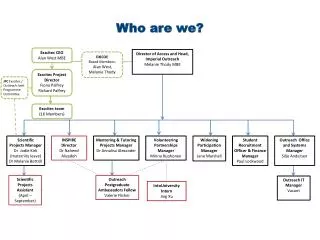
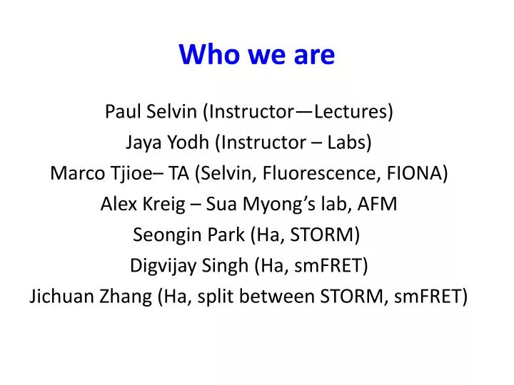
Who we are. Paul Selvin (Instructor—Lectures) Jaya Yodh (Instructor – Labs) Marco Tjioe– TA (Selvin, Fluorescence, FIONA) Alex Kreig – Sua Myong’s lab, AFM Seongin Park (Ha, STORM) Digvijay Singh (Ha, smFRET) Jichuan Zhang (Ha, split between STORM, smFRET). What we’re here for.

E N D
Who we are Paul Selvin (Instructor—Lectures) Jaya Yodh (Instructor – Labs) Marco Tjioe– TA (Selvin, Fluorescence, FIONA) Alex Kreig – Sua Myong’s lab, AFM Seongin Park (Ha, STORM) Digvijay Singh (Ha, smFRET) Jichuan Zhang (Ha, split between STORM, smFRET)
What we’re here for Give you direct experience in lab manipulations associated with modern biophysics We are not here to lecture you! I’m irrelevant! A big part is you must take responsibility for learning We’re here to help. Model is based on summer schools, Taught for past 5 years, about 40 students/year, 1 week/year, very full-time. A big emphasis will be on detection of Single Molecules
Physics 598BP Format: 6 experimental labs will be offered in total. Plus M 4-5pm lecture Lab 1 (Loomis): Ensemble Fluorescence Basics Lab 2 (IGB): Bright Field & Fluorescence Microscopy Lab 3 (Loomis): FIONA Lab 4 (IGB): AFM Lab 5 (Loomis): smFRET Lab 6 (Loomis): STORM Each experimental lab is taught over 2 weeks to 4 groups (Groups A-D) of 3 students in two consecutive 4-hr lab sessions (Tuesday or Thursday from 1-5pm). The hands-on experiments and analysis will be mixed over each 2 week period (for example – 6 hrs total of taking data & 2 hrs of analysis). Students will be expected to do the remainder of the analysis on their own. In summary, 2 experimental labs will be taught over a total of 4 weeks to 12 students You must choose a lab time, Tuesday or Thursday
Good Resources Our Web sitehttp://courses.physics.illinois.edu/phys598bp/Course materials --Zeiss web sitehttp://zeiss-campus.magnet.fsu.edu/articles/basics/index.html(a fair amount of (today’s) lecture taken from this)Molecular Biology of the Cell http://www.ncbi.nlm.nih.gov/books/NBK26880/Wikipedia
Lab Concepts Basic Concepts in Microscopy: Magnification Numerical Aperture and Resolution Point Spread Function and Deconvolution (2) Bright Field Imaging Köhler illumination (3) Enhancing Contrast in Optical Microscopy Phase Contrast Bright Field Imaging Differential Interference Contrast (DIC) Reflected Light Microscopy (4) Fluorescence Imaging (5) 3D-Imaging of thick specimen Z-stack wide-field fluorescence Imaging and deconvolution Apotome Sectioning (Structured Illumination Microscopy) Lab 1: Bright Field and Fluorescence Optical Microscopy and Sectioning
Lens Maker Equation (for thin lenses) A lens transfers an object plane to an image plane with some magnification. o i Different lenses, depending on curvature, have different magnification 4x 100x i o o i Def’n: Object and image planes are conjugate planes. An image is formed where one object point goes to one (and only one) image point. In 3D, you have problems with out of focus light. (Need Deconvolution microscopy) http://en.wikipedia.org/wiki/Lens_(optics)
Numerical ApertureObjective lens does this with some magnification and collecting some fraction of the emitted/scattered light Numerical aperture = NA = nsinqn = Index of refraction of media(n= 1.0 air; 1.33 water; 1.5 for immersion oil) media Higher N.A., can detect weaker fluorescence (highest NA= 1.49-1.68) Also, higher NA gives you better Resolution
Infinity Objective Lenses (now standard, greater flexibility) Optical elements (filters, etc.) Tube lens Fixed length (160-220 mm, depending on company) object image Infinity space Detector
Point Spread FunctionEven a “point” forms a finite spot on detector.No matter how small an emitting light, it always forms a finite-sized spot, PSF ~ l/2NAYou can “never” get better than l/2NA ~ 500 nm/2* 1.4 ~ 175 nm (Caveat: can do 100x better with single molecules!) PSF depends on NA
W.E. Moerner, Crater Lake Accuracy & Resolution You may be able to measure center really well. center Signal ~ N, # of photons Noise ~ √N (Photon number inherently varies) How well can you tell where the center is? Depends on width and S/N. Accuracy = width/√N = 250nm/√N Width = l/2 10,000 photons. Uncertainty = √10,000 Accuracy = 250 nm/ sem = 250 nm/ 100 = 2.5 nm You can get a few nanometer accuracy with light that is several hundred
Light from all sources is Poissonian (varies) N = 100: sometime N=90, 99, 102, 98 etc. N ± √N Light varies in two way: It varies within a point spread function --it lands anywhere within a PSF with a certain probability. -- The number of photons (i.e. the intensity) varies in time. Noise—either one varies like √N Big effort to get a light sources with a fixed # of photons
The resolution is limited to how well you can separate two overlapping PSFs. Resolution: The Abbe or Rayleigh criteria How well can you resolve two nearby (point) objects? Light always spreads out to ~ l/2NA Rayleigh Criteria ~ ~ l/2NA ~ 200-250 nm But, with single-molecule imaging, can beat this. (e.g. have one green and one red)
Microscopes Cells discovered with invention of microscope. Or with CCD 1000x, 0.2 um Molecular Biology of the Cell. 4th edition. Alberts B, Johnson A, Lewis J, et al. New York: Garland Science; 2002.
Bright-field Microscopy (Standard configuration)Limits to sensitivity N photon N- d photons detector 1 detector 2 When can you detect that grey object is there? Tell that detector 2 has more photons than detector 1 Ideal: you have the light source as good as possible—no spatial (or temporal) heterogeneity You have intensity I: N photons on average: there is √N variation inherently
Bright-field con’t N = 100: sometime N=90, 99, 102, 98 etc. N ± √N Can tell that grey object is there is if: N2 – N1 > (N12 + N22)1/2 Ideally, you’d hit the sample with a really bright light source What if detector isn’t perfect? Noise is larger than √N? This is very common. Use Koehler illumination
Köhler illumination: minimize sample variation due to excitation (used with sources like light bulbs; irrelevant for lasers) B. KöhlerIllumintion: Conjugate planes are the illuminating bulb filament and Condenser diaphragm. Second conjugate planes are the Field diaphragm and the sample plane. When adjusted correctly, the image of the field diaphragm and the sample are coincident. The filament is out of the plane of focus, and thus uniformly diffuse. (old technique) A. Critical Illumination. Conjugate planes are the illuminating bulb filament and sample plane (O). When adjusted correctly, the image of the filament is seen coincident with the sample image. A diffusing glass filter (d) is used to blur the filament image. The trick is to make sure that you are not imaging the light source. The filament is out of the plane of focus, and thus uniformly diffuse. FD: Field diaphragm: CD: Condenser diaphragm http://microscopy.berkeley.edu/courses/tlm/condenser/optics.html
What if you can’t see something by bright-field?(Contrast too low) Optical elements (filters, etc.) object image Infinity space Use dyes to generate more contrast Detector
Enhancing Contract in Optical Microscopy Investigations dealing with inherently low-contrast specimens, such as unstained bacteria, thin tissue slices, and adherent live cells, rely on specialized contrast-enhancing techniques to assist with imaging these virtually transparent samples. Use dyes (w color contrast) Two Phase techniques Polarized light requires birefringence (usually not present to a significant degree in animal cells) to generate contrast. Muscle cells are birefringent.
What if you can’t see something by bright-field?(Contrast too low) Modulate phase object image Infinity space Rely on phase of light (instead of amplitude) Detector
What if you can’t see something by bright-field? Light has a phase, (plus an amplitude) You may be able to see a phase change.
Bright-field Microscopy –Phase ContrastLimits to sensitivity N photon sin wt +f A sin wt + f Asinwt Detector Have to interfere with each other, i.e. end up hitting detector at same place.
Two Phase Techniques:Phase Contrast and Digital Interference Microscopy.Both rely on phase difference between the sample and background Phase contrast yields image intensity values as a function of specimen optical path length magnitude, with very dense regions (those having large path lengths) appearing darker than the background. Alternatively, specimen features that have relatively low thickness, or a refractive index less than the surrounding medium, are rendered much lighter when superimposed on the medium gray background. Good for thin samples. DIC: optical path length gradientsare primarily responsible for introducing contrast into specimen images: Really good for edges. Thick samples; can be used with high numerical aperture lenses http://micro.magnet.fsu.edu/primer/techniques/dic/dicphasecomparison.html
Phase Contrast Microscopy Very little absorption, so Brightfield and Darkfield isn’t good. Phase contrast is an excellent method to increase contrast when viewing or imaging living cells in culture, but typically results in halos surrounding the outlines of edge features. The technique is ideal for thin unstained specimens such as culture cells on glass. (which are approximately 5 to 10 micrometers thick above the nucleus, but less than a micrometer thick at the periphery), thick specimens (such as plant and animal tissue sections). The amount of the phase shift depends on what media (refractive index) the waves have passed through on their paths, and how long the paths were through these media. Slight differences in phase are translated into differences in intensity
Phase contrast microscopy Notice red line, which contains a different phase due to sample is not phase shifted. They interfere with light that is unrefracted.
Differential Interference Microscopy Differential interference contrast microscopy requires plane-polarized light and additional light-shearing (Nomarski) prisms to exaggerate minute differences in specimen thickness gradients and refractive index. Good for thick samples. Can use high numerical apertures (in contrast to Phase contrast. Lipid bilayers, for example, produce excellent contrast in DIC because of the difference in refractive index between aqueous and lipid phases of the cell. In addition, cell boundaries in relatively flat adherent mammalian and plant cells, including the plasma membrane, nucleus, vacuoles, mitochondria, and stress fibers, which usually generate significant gradients, are readily imaged with DIC.
DIC—a Polarization-type of microscopy Condensor splits light into two orthogonal polarizations and slightly shifts them laterally shifts these partial beam such a way that a small lateral displacement of the wavefronts occurs where regions of thickness or refractive index vary. If the two partial beams now pass through exactly the same structures, no further path difference will occur in the specimen (Figure 5(a) and Figure 5(c)). However, if the two partial beams see slightly different conditions, each of them will experience a slightly difference pathlength that accompanies it on the remaining trip to the intermediate image plane (Figure 5(b)).