Download
1 / 23
250 likes | 596 Vues
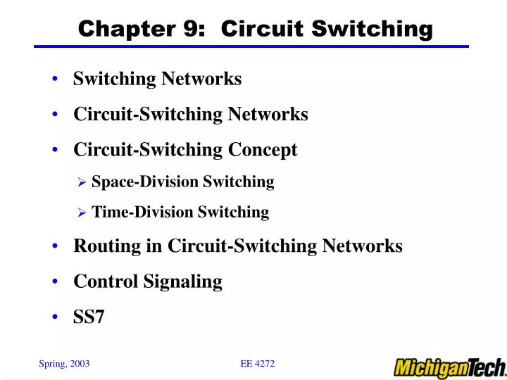
Chapter 9: Circuit Switching. Switching Networks Circuit-Switching Networks Circuit-Switching Concept Space-Division Switching Time-Division Switching Routing in Circuit-Switching Networks Control Signaling SS7. Switching Networks.

E N D
Chapter 9: Circuit Switching • Switching Networks • Circuit-Switching Networks • Circuit-Switching Concept • Space-Division Switching • Time-Division Switching • Routing in Circuit-Switching Networks • Control Signaling • SS7
Switching Networks • Long distance transmission is typically done over a network of switched nodes • Nodes not concerned with content of data • End devices are stations: Computer, terminal, phone, etc. End device node
Switching Networks (Con’t) • A collection of nodes (switches) and connections is a communications network • Data routed by being switched from node to node • Nodes may connect to other nodes (switches) only, or to stations (hosts)and other nodes • Node to node links usually multiplexed (TDM &FDM) • Network is usually partially connected • Some redundant connections are desirable for reliability • Two different switching technologies • Circuit switching • Packet switching
Circuit Switching & features • Dedicated communication path between two stations • Three phases: Establish; Transfer; Disconnect • Must have switching capacity and channel capacity to establish connection • Must have intelligence to work out routing • Inefficient • Channel capacity dedicated for duration of connection • If no data, capacity wasted • Set up (connection) takes time • Once connected, transfer is transparent, no delay -> • Developed for voice traffic (phone)
Telecomm. Networks & Components • Subscriber: Devices attached to network • Local Loop: Subscriber loop -> Connection to network • Exchange: Switching centers; end office supports subscribers • Trunks (Multiplexed): Branches between exchanges
Circuit Switch Concepts & Elements • Digital Switch • Provide transparent signal path between devices • Network Interface • Control Unit • Establish connections • Generally on demand • Handle and acknowledge requests • Determine if destination is free • construct path • Maintain connection • Disconnect
Digital Switch: Blocking vs. Non-blocking • Blocking • A network is unable to connect end stations because all paths are in use • In blocking network this is possible • Used on voice systems • Short duration calls • Non-blocking • Permits all stations to connect (in pairs) at once • Used for some data connections • Switching Techniques • Space-Division Switching • Time-Division Switching
Flat Crossbar Switch: Example of space-division Switch • Separate physical paths for signal for one another • E.g., Crossbar switch • When a request comes in from an incoming line for an outgoing line, the corresponding crosspoint is closed to enable information to flow from the input to the output • The connection requests are neverblocked due to the lack of connectivity resource (crosspoint), but a busy outgoing line rejects a connection request • The complexity of the crossbar switch is measured by the number of crosspoints (N2)
kxn nxk N/n x N/n 1 1 1 kxn nxk N inputs 2 2 N outputs N/n x N/n kxn nxk 2 3 3 kxn nxk N/n N/n N/n x N/n k Multistage Space-Division Switch • Reduced number of crosspoints:2(N/n)nk + k (N/n)2 crosspoints • More than one path through network->Increased reliability • More complex control • May be blocking: can be solved by increasing # of intermediate switch
Time Division Switching • All digital switching technology is base on the use of STDM • During a time slot, data are switched from the enabled input line to the enabled output line, # of time slot = # of devices • The data rate on the controller must be high enough: e.g. 100 device @ 19.2kbps, controller date rate at 1.92Mbps • Partition low speed bit stream into pieces that share higher speed stream • e.g. TDM bus switching • based on synchronous time division multiplexing • Each station connects through controlled gates to high speedbus
Routing • Many connections will need paths through more than one switch • Need to find a route • Efficiency • Resilience • Static routing uses the same approach all the time • Dynamic routing allows for changes in routing depending on traffic
Alternate Routing: an example routing approach • Possible routes between end offices predefined • Originating switch selects appropriate route • Routes listed in preference order • Different sets of routes may be used at different times • Can be implemented statically or dynamically
Control Signaling Functions • Audible communication with subscriber • Transmission of dialed number • Call can not be completed indication • Call ended indication • Signal to ring phone • Billing info • Equipment and trunk status info • Diagnostic info
Location of Signaling • Subscriber to network • Depends on subscriber device and switch • Within network • Management of subscriber calls and network • more complex • Mapping is needed between the two signaling techniques @ the local switching office
InChannel Signaling: an traditional signaling approach • Use same channel for signaling and call • Requires no additional transmission facilities • Inband • Uses same frequencies as voice signal • Can go anywhere a voice signal can • Impossible to set up a call on a faulty speech path • Out of band • Voice signals do not use full 4kHz bandwidth • Narrow signal band within 4kHz used for control • Can be sent whether or not voice signals are present • Need extra electronics • Slower signal rate (narrow bandwidth)
Drawbacks of InChannel Signaling • Limited control signaling transfer rate • Inband signaling: when there is no voice data • Out-band signaling: a very narrow bandwidth is for signaling • Delay between entering address (dialing) and connection • Overcome by use of common channel signaling
Common Channel Signaling • Control signals carried over paths independent of voice channel • One control signal channel can carry signals for a number of subscriber channels • Associated Mode • Common channel closely tracks interswitch trunks • Disassociated Mode • Additional nodes (signal transfer points) • Effectively two separate networks
Signaling System Number 7 • SS7: a real world Common channel signaling scheme • Used in ISDN (Integrated Service Digital Network) • Optimized for 64k digital channel network • Functionalities: Call control, remote control, management and maintenance • Reliable means of transfer of info in sequence • Suitable to operate over analog and below 64k • Suitable to point-to-point terrestrial and satellite links
SS7 Signaling Network Elements • Signaling point (SP) • Any point in the network capable of handling SS7 control message • Signal transfer point (STP) • A signaling point capable of routing control messages • Control plane • Responsible for establishing and managing connections • Information plane • Once a connection is set up, info is transferred in the information plane